Eureka AIR delivers breakthrough ideas for toughest innovation challenges, trusted by R&D personnel around the world.

Optical information recording medium and its manufacture

A recording medium and laser recording technology, which are applied in the manufacture of optical record carriers, optical record carriers, and recording/reproducing by optical methods, etc., can solve problems such as the reduction of recording characteristics, achieve good recording characteristics, and inhibit the effect of decomposition.

Inactive Publication Date: 2002-04-17
FUJIFILM CORP
View PDF3 Cites 3 Cited by
  • Summary
  • Abstract
  • Description
  • Claims
  • Application Information

AI Technical Summary

Problems solved by technology

However, there is also a certain problem in this case, that is, when the hard coat layer is formed by irradiating light to the photocurable resin for photocuring, the light is also irradiated on the pigment recording layer, and the pigment contained in the recording layer will be damaged during manufacture. Part is disassembled, resulting in reduced recording characteristics

Method used


Image

  • Optical information recording medium and its manufacture
  • Optical information recording medium and its manufacture
  • Optical information recording medium and its manufacture

Examples


Embodiment 1

[0056] [Production of CD-R discs]

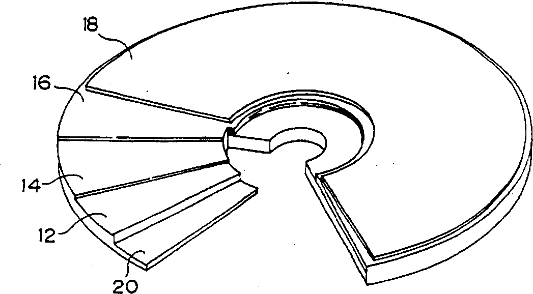
[0057] Spiral grooves (pitch: 1.6μm 1. Groove width: 0.5 μm, groove depth: 0.18 μm, groove inclination angle: 55°). Figure 6 A schematic cross-sectional view showing the groove shape. As defined in this figure, the depth D of the groove is the distance from the surface of the substrate before the groove is formed to the deepest part of the groove, the width W of the groove is the groove width of D / 2 depth, and the groove width The inclination angle is the angle between the straight line connecting the inclination portion from the surface of the substrate before the formation of the trench to the depth of D / 10 and the inclination portion from the deepest groove to the height of D / 10, and the substrate surface.

[0058] Next, using an ultrasonic oscillator (1800W), within 1 hour, 2.65g of the above-mentioned cyanine pigment (A) was deeply dissolved in 100ml of 2,2,3,3-tetrafluoropropanol, and prepared to form a recording layer. coating sol...

Embodiment 2

[0066] [Production of short-wavelength discs]

[0067] Spiral grooves (pitch: 0.4μm, Groove width: 0.2 μm, groove depth: 0.08 μm, groove inclination angle: 60°).

[0068] Next, on the groove-side surface of the polycarbonate substrate, Ag was sputtered by DC magnetron sputtering to form a light reflection layer with a thickness of 80 nm.

[0069] Next, 1.5 g of the above dye (B) was dissolved in 100 ml of 2,2,3,3-tetrafluoropropanol within 1 hour using an ultrasonic oscillator (1800 W) to prepare a coating solution for forming a recording layer. Apply the coating liquid on the groove side surface of the polycarbonate substrate on which the light reflection layer is formed by spin coating, prepare 0.5 ml at 300 rpm, change the rotation speed to 300 rpm to 4000 rpm, and dry to form a pigment record layer. The pigment recording layer was formed to a thickness of 100 nm in the groove and to a thickness of 60 nm in the land portion. On the above-mentioned pigment recording laye...


PUM

PropertyMeasurementUnit
thicknessaaaaaaaaaa
thicknessaaaaaaaaaa
thicknessaaaaaaaaaa

Abstract

Provided are an optical information recording medium having an excellent recording characteristic and its production method by suppressing the decomposition of dyestuff which is contained in a dyestuff recording layer when an optical hardening resin is optically hardened to form an optical hardening layer. The optical information recording medium is composed of a disk shape transparent baseboard 12 with a center hole formed in a center part, a light reflection layer 16, the dyestuff recording layer 14 containing an organic dyestuff, an intermediate layer 22, an adhesion layer 24 and a thin film protection layer 26. The light reflection layer 16, the dyestuff recording layer 14 and the intermediate layer 22 are arranged on an area where a pre- groove of the transparent baseboard 12 is formed. The thin film protection layer 26 is arranged on the intermediate layer 22, through the adhering layer 24 which is composed of the optical hardening resin to be hardened by light of a band except the main absorption band of the recording layer dyestuff.

Description

technical field [0001] The present invention relates to an optical information recording medium and a method for manufacturing the optical information recording medium, in particular to an optical information recording medium having a pigment-containing recording layer and a hardened layer formed by photocuring a photocurable resin, and a method for manufacturing the optical information recording medium. Background technique [0002] In the past, the write-once optical information recording medium (optical disc) that can record information once by using a laser is called CD-R, which is widely known. The representative structure of this CD-R optical information medium is a transparent disc-shaped substrate. The following lamination layers are sequentially formed on the top, that is, a pigment recording layer formed of organic pigments, a light reflection layer formed of metals such as gold, and a protective layer formed of resin. Information is recorded on this op...

Claims


Application Information

Patent Timeline
Patent Type & Authority Applications(China)
IPC IPC(8): G11B7/24G11B7/24062G11B7/244G11B7/245G11B7/246G11B7/254G11B7/257G11B7/26
CPCG11B7/244G11B7/254G11B7/245G11B7/26
Inventor 宇佐美由久
Owner FUJIFILM CORP
Why Eureka
Eureka Blog
Learn More