Electronic component mounting apparatus, and power supply control method executed by electronic component mounting apparatus

A technology for electronic component installation and electronic components, which is applied in the direction of electrical components, electrical components, etc., can solve the problem of increased power consumption of the drive device, and achieve the effect of saving energy consumption

Inactive Publication Date: 2002-05-01
PANASONIC CORP
View PDF1 Cites 15 Cited by
  • Summary
  • Abstract
  • Description
  • Claims
  • Application Information

AI Technical Summary

Problems solved by technology

On the other hand, for electronic component mounting equipment, it is necessary to increase the production capacity per unit time, which will lead to an increase in power consumption per drive unit

Method used


Image

  • Electronic component mounting apparatus, and power supply control method executed by electronic component mounting apparatus
  • Electronic component mounting apparatus, and power supply control method executed by electronic component mounting apparatus
  • Electronic component mounting apparatus, and power supply control method executed by electronic component mounting apparatus

Examples


Embodiment Construction

[0028] Hereinafter, an electronic component mounting device of an embodiment of the present invention and a power control method implemented by the electronic component mounting device will be described with reference to the accompanying drawings. The same parts are indicated by the same reference numerals in each figure.

[0029] As an example of the "to be mounted target" described in the above "Summary of the Invention" corresponds to the circuit board in this embodiment. However, the intended installation target is not limited to this, and theoretically includes, for example, a circuit board with liquid crystal display components.

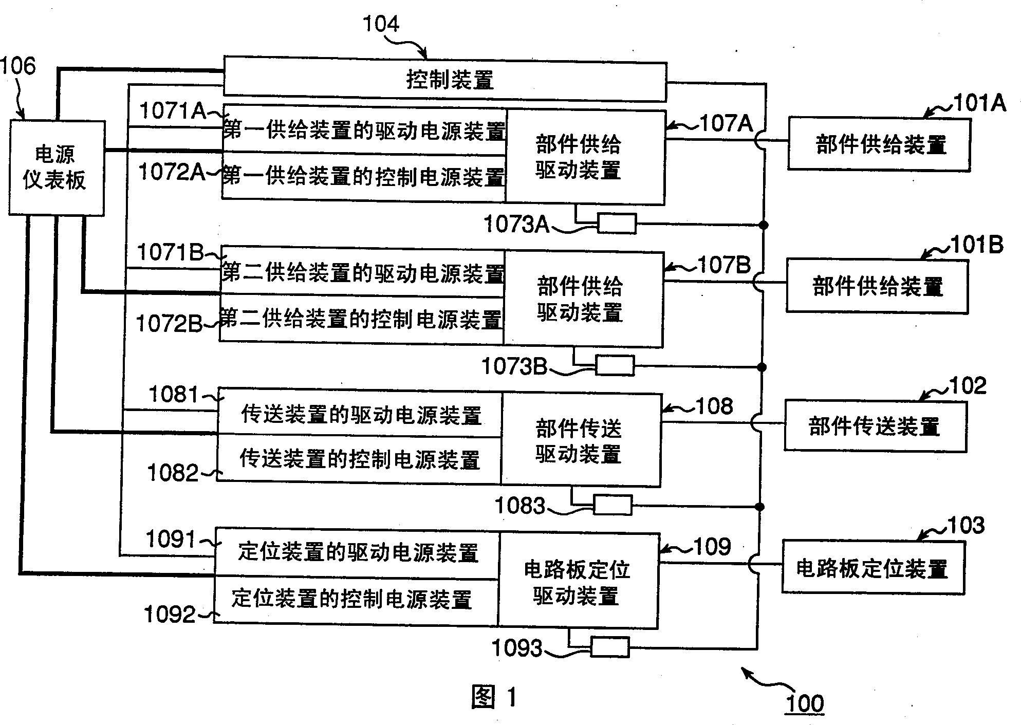
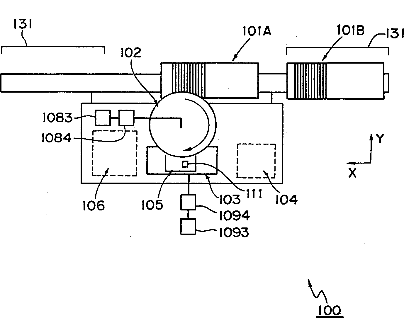
[0030] FIG. 1 shows an electronic component mounting apparatus 100 of this embodiment. The electronic component mounting equipment 100 roughly includes component supply devices 101A and 101B movable in the X direction for supplying electronic components 111 to be mounted on the circuit board 105; and a rotating component transport device 102 for ob...


PUM


Abstract

The present invention provides an electronic component mounting apparatus which can reduce a consumption power amount in comparison with the background art, and a power supply control method which is executed by the electronic component mounting apparatus. A drive power source and a control power source are separately connected and shut-off in accordance with a command from a control device (104) to each of component feed drive parts (107A, 107B) for driving component feed devices (101A, 101B), a component transfer drive device (108) for driving a component transfer device (102), and a circuit board positioning drive device (109) for driving a circuit board positioning device (103). The control device detects an individual occurrence of halt condition of each of constitution parts of an electronic component mounting apparatus (100) and shuts off the drive power source to the drive device in the halt condition. Thus, a wasteful power consumption is eliminated and the production is continued with a necessary minimum power.

Description

Technical field [0001] The present invention relates to an electronic component mounting device for mounting electronic components at a mounting position on a target to be mounted, such as a printed circuit board, and a power control method implemented by the electronic component mounting device. Background technique [0002] Figure 7 A general electronic component mounting device 50 is shown. This kind of electronic component mounting equipment 50 roughly includes: component supply devices 1A, 1B for sending electronic components to be mounted to the circuit board 5; and a rotary component transfer device 2 for sending from the component supply device 1A or the component supply device 1B Obtain electronic components and install them on the circuit board 5; the circuit board positioning device 3 is used to move the circuit board 5 so that the mounting position on the circuit board 5 is positioned at the release position of the acquired component in the component transfer device...

Claims


Application Information

Patent Timeline
Patent Type & Authority Applications(China)
IPC IPC(8): H05K13/04H05K13/08
CPCH05K13/08H05K13/0885Y10T29/49124Y10T29/4913Y10T29/49133Y10T29/49137Y10T29/49139Y10T29/53178Y10T29/53191Y10T29/53261H05K13/04
Inventor 泉田圭三武田健中野和幸
Owner PANASONIC CORP
Why Eureka
Try Eureka