Lens combination converged LED array display

A technology of light emitting diodes and combined lenses, applied in instruments, identification devices, etc., can solve the problem of inconsistent light-emitting color mixing angles of chips, and achieve the effects of enhancing picture clarity, improving functions, and improving luminous brightness.

Inactive Publication Date: 2002-07-10
王国忠
View PDF0 Cites 12 Cited by
  • Summary
  • Abstract
  • Description
  • Claims
  • Application Information

AI Technical Summary

Problems solved by technology

[0006] 1. Each chip corresponds to a convex lens, which can not only improve the luminous brightness of each pixel, but also solve the problem of inconsistent color mixing angles of the chips of the same pixel

Method used


Image

  • Lens combination converged LED array display
  • Lens combination converged LED array display
  • Lens combination converged LED array display

Examples


Embodiment Construction

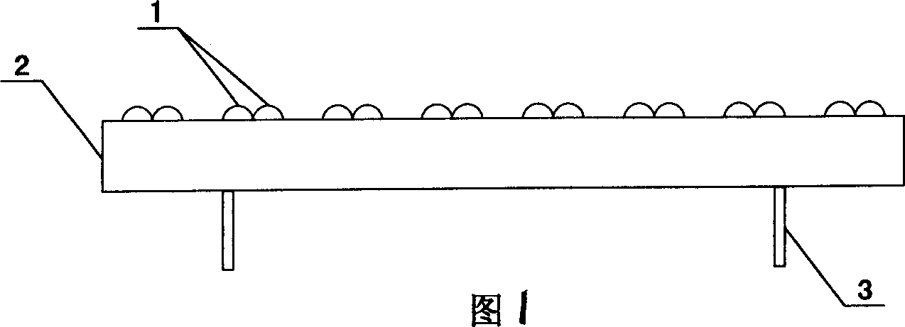
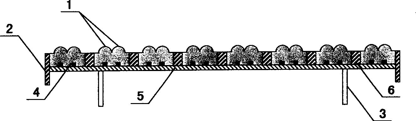
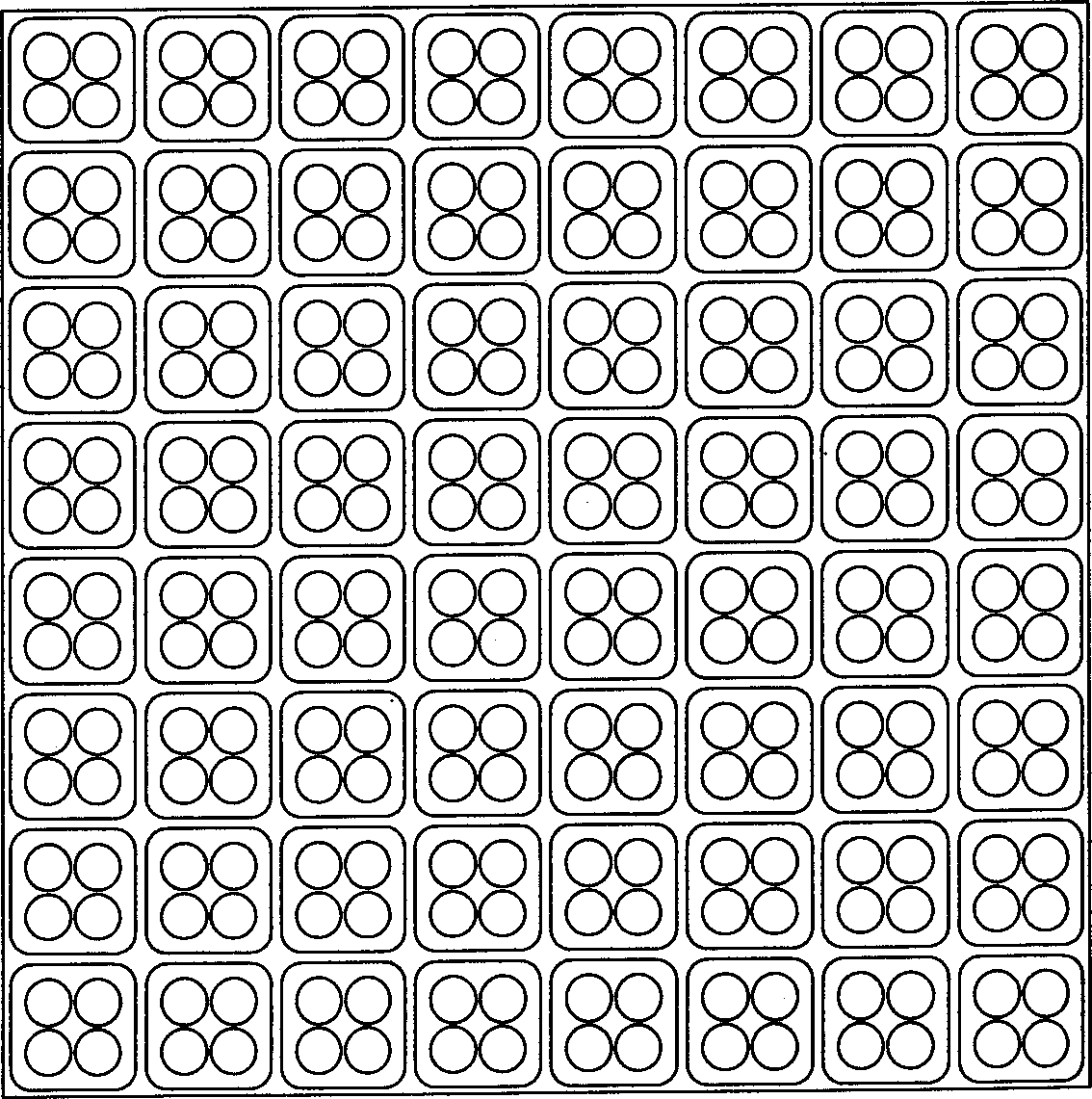
[0011] Figure 1 and figure 2 As shown, the bottom of the combined lens concentrating LED dot matrix display is a circuit substrate 5, on which LED chips 4 are arranged in a dot matrix, and external wires 3 are drawn out. The circuit substrate 5 is covered with a plastic casing 2, and the plastic casing 2 is provided with reflective cavity holes 6 in a dot matrix. Four light-emitting diode chips 4 form a light-emitting pixel point, and the reflective cavity holes 6 correspond to each light-emitting pixel point arranged in a dot matrix. Each reflective cavity 6 is sealed with four epoxy resin convex lenses 1, and the epoxy resin convex lens 1 corresponds to each LED chip 4 in the reflective cavity 6, thereby forming a complete display. The light intensity and angle of the light-emitting pixels can be controlled by adjusting the curvature and protrusion height of the epoxy resin convex lens 1 during sealing.

[0012] A plurality of light-emitting diode chips of different colors ...


PUM


Abstract

The LED array display unit consists of LED chip arranged in basic circuit board and with lead-out wires, circuit board with reflecting cavity holes corresponding to the luminous pixels, several epoxy resin convex lenses corresponding to the LED chips with the light emitting angle being regulated by the curvature and height of the lenses. The display unit features that each light emitting pixel consists of several convex lenses dependent on the amount of the LED chips, so that each chip is in the center of the convex lens resulting in excellent color mixing effect of the chips; and that the dot matrix packing can raise the pixel density and definition of outdoor display screen and lower cost.

Description

technical field [0001] The invention belongs to the technical field of an indicating device or a circuit for displaying variable information by a static method, and in particular relates to an electronic color display using a diode as a light source. technical background [0002] The light-concentrating LED dot-matrix display in the prior art is usually composed of a circuit substrate, LED chips arranged in a dot matrix and a shell with a reflection cavity, and each reflection cavity shell is sealed by a molded epoxy resin convex lens. It overcomes the shortcomings of flat-panel displays, has high luminous intensity and good light-gathering performance. However, if multiple light-emitting diode chips of different colors are packaged in one pixel, due to the deviation of the positions of each chip in the same convex lens, it is impossible to keep the normal parallel, so the color difference of the color light perceived by the visual receptor at different ...

Claims


Application Information

Patent Timeline
Patent Type & Authority Applications(China)
IPC IPC(8): G09F9/33
Inventor 王国忠
Owner 王国忠
Why Eureka
Try Eureka