Apparatus having an electroacoustic transducer forming sound reproducing means and part of vibration generating means

A technology for vibration generating equipment and electro-acoustic transducers, which is applied to fluids, electromechanical devices, and sound-producing devices that utilize vibration, can solve the problems of long service life, impossible solutions, etc., to avoid mechanical loads and achieve simple structure. Effect

Inactive Publication Date: 2002-08-07
KONINKLIJKE PHILIPS ELECTRONICS NV
View PDF1 Cites 1 Cited by
  • Summary
  • Abstract
  • Description
  • Claims
  • Application Information

AI Technical Summary

Problems solved by technology

This means that the application of contradictory requirements can only be solved by a compromise approach, considering the trade-off between the highest possible quality sound signal and the maximum vibration effect, so that it is impossible to obtain a solution that can solve any one purpose. the best solution for
Furthermore, in the known solutions, the moving coil and the diaphragm are subjected to relatively high mechanical loads, which is disadvantageous with regard to minimal wear and a long service life

Method used


Image

  • Apparatus having an electroacoustic transducer forming sound reproducing means and part of vibration generating means
  • Apparatus having an electroacoustic transducer forming sound reproducing means and part of vibration generating means
  • Apparatus having an electroacoustic transducer forming sound reproducing means and part of vibration generating means

Examples


Embodiment Construction

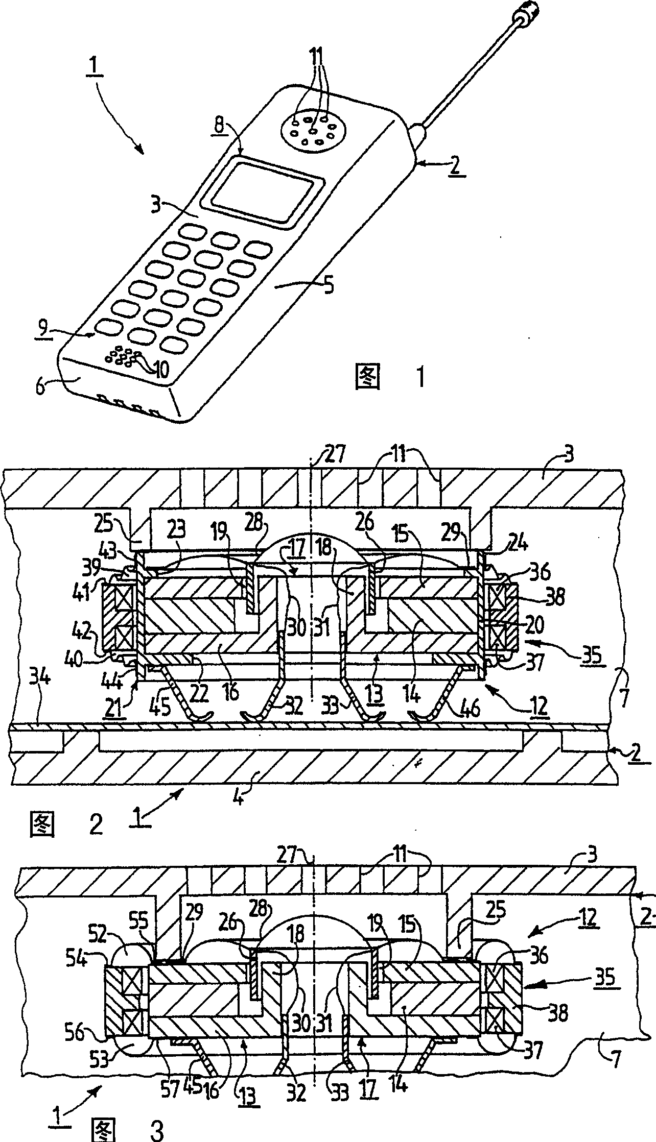
[0018] Figures 1 and 2 show a device 1 which takes the shape of a so-called mobile phone. The device 1 has a casing 2 with an upper shell 3, a bottom shell 4, a first long side wall (not aside), a second long side wall 5, a first short side wall 6 and a second short side wall 7 . A display device 8 and a keypad 9 are located in an area within the upper housing 3 . Furthermore, the first sound transmission hole 10 and the second sound transmission hole 11 are also located in a region inside the upper case 3 . The first sound transmission hole 10 transmits sound waves to a microphone installed in the device 1 . The second sound transmission hole 11 transmits sound waves from the electro-acoustic transducer 12 installed in the device 1 to the outside of the device 1 so that the sound waves reach the ear of the user using the device 1 .

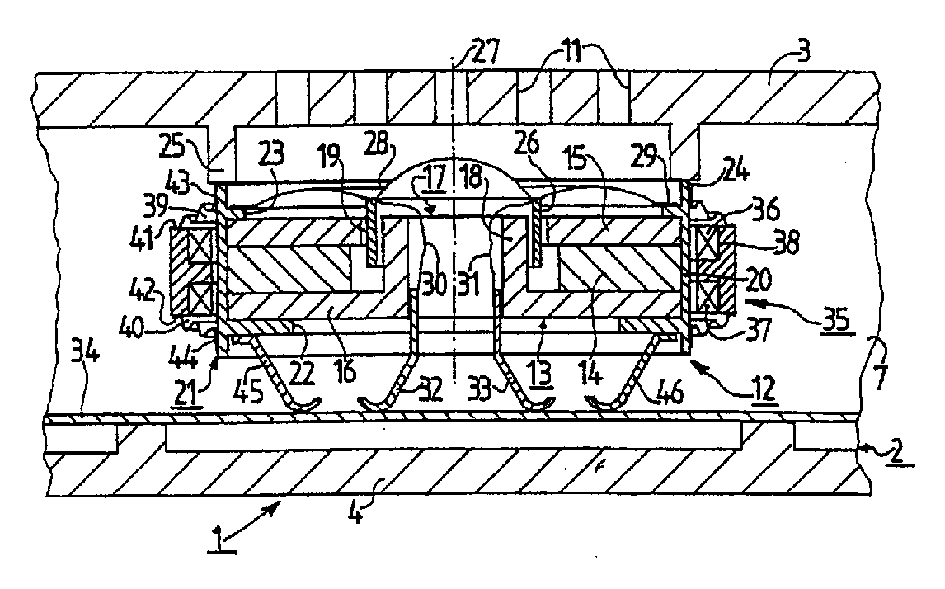
[0019] The electroacoustic transducer 12 takes the shape of a so-called loudspeaker box. The converter 12 has a magnet system 13 . The magn...


PUM


Abstract

In an apparatus (1) having an electroacoustic transducer (12) which includes a magnet system (13) which is used to realize vibration generating means (35) the vibration generating means (35) include, in addition to the magnet system (13), at least one movably mounted vibration generating coil (36, 37) arranged in the stray field area of the magnet system (13), the vibration generating coil (36, 37) being preferably also connected to a metal part (38) which consists of a soft-magnetic material.

Description

technical field [0001] The invention relates to a device as defined in the opening part of claim 1 . [0002] The invention also relates to an electroacoustic transducer as defined in the opening part of claim 6 . Background technique [0003] Such a device in the form of a mobile phone and such an electroacoustic transducer are known, for example, from patent document US5903076A. It is known from the solution of said patent document that the moving coils arranged in the electro-acoustic transducer for receiving the sound signal generated by the acoustic wave with the help of the diaphragm of the transducer are also used to generate easily perceptible vibrations, wherein the transducer The diaphragm is mounted on the moving coil. In order to generate such easily noticeable vibrations, the moving coil of the transducer located in the effective magnetic field area of ​​the magnet system is arranged to receive a relatively low frequency AC signal, thereby causing the moving c...

Claims


Application Information

Patent Timeline
Patent Type & Authority Applications(China)
IPC IPC(8): H04R13/00B06B1/04G10K9/13H02K33/18
CPCB06B1/045G10K9/13
Inventor E·鲁贝尔H·伦纳J·R·巴克曼
Owner KONINKLIJKE PHILIPS ELECTRONICS NV
Why Eureka
Try Eureka