
8-box 9-layer high-temp calciner

A calciner and calcined coal technology, which is applied in furnaces, muffle furnaces, cooking furnaces, etc., can solve the problems of large power consumption, high production costs, and uneven furnace temperature, so as to reduce the blackness of flue gas and improve the production environment. Improvement, temperature equalization effect

Inactive Publication Date: 2002-08-14
李令杰
View PDF1 Cites 6 Cited by
  • Summary
  • Abstract
  • Description
  • Claims
  • Application Information

AI Technical Summary

Problems solved by technology

[0002] The carbon calcination furnace currently used in China is a technology introduced from Japan and the former Soviet Union in the 1970s. The furnace type is 6 tanks and 3 layers. After the 1980s, it was changed to 6 tanks and 5 layers. After 1999, it was upgraded to 6 tanks and 9 layers of fire. The physical and chemical indicators of carbon, in the 1970s, the volatile matter could only be calcined to 2%, and the resistivity was 1600 ohms. After the 80s and 90s, the volatile matter could be calcined by 2%. , Since 1995, it has increased to 0.9%-1%, and the resistivity is about 1100 ohms. Compared with the electric calciner, there is still a big gap. Using the electric calciner, the volatile content reaches 0.6%, and the resistivity drops to about 800 ohms. , but the cost of the electric calciner is too high, and the power consumption is too large, resulting in high production costs
[0003] The Chinese patent "Carbon Furnace" (application number 00247722.X) discloses a technical solution, which is still a typical six-tank structure, the direction of the fire path is not particularly reasonable, the furnace temperature is not uniform enough, and the output and quality of carbon It cannot be compared with the electric calciner, and the waste heat cannot be fully recovered and utilized

Method used


Image

  • 8-box 9-layer high-temp calciner
  • 8-box 9-layer high-temp calciner
  • 8-box 9-layer high-temp calciner

Examples


Embodiment

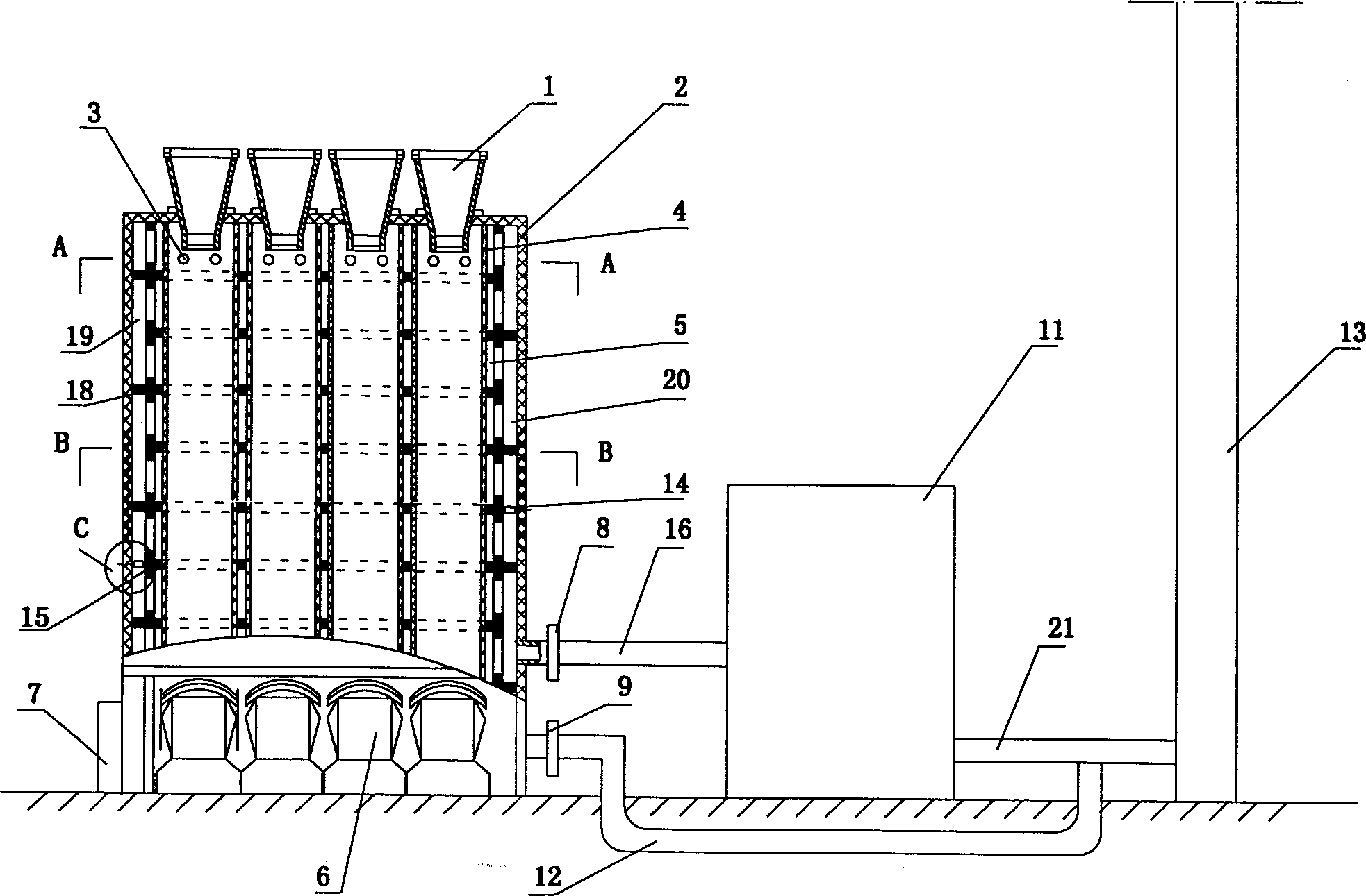
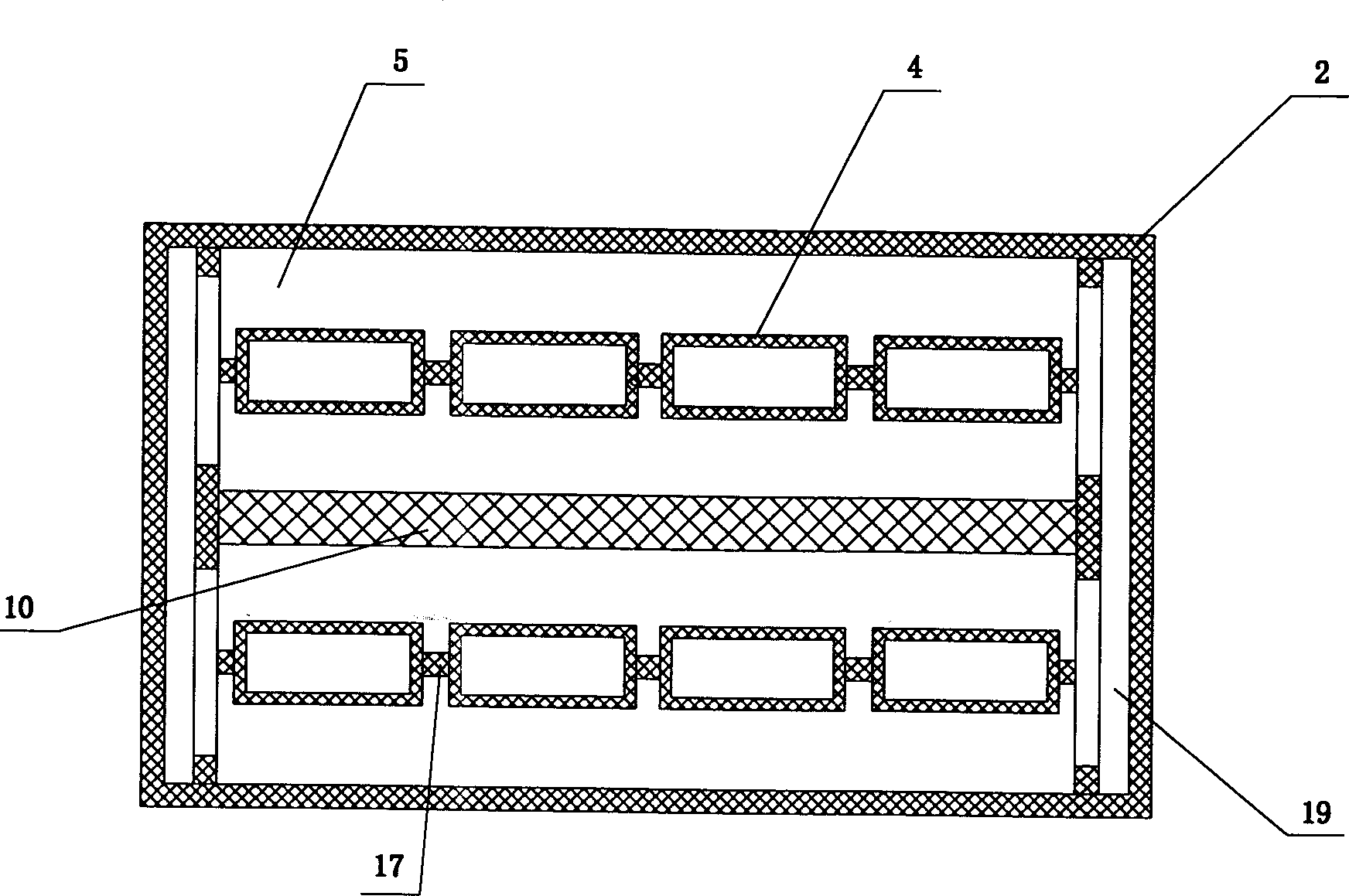
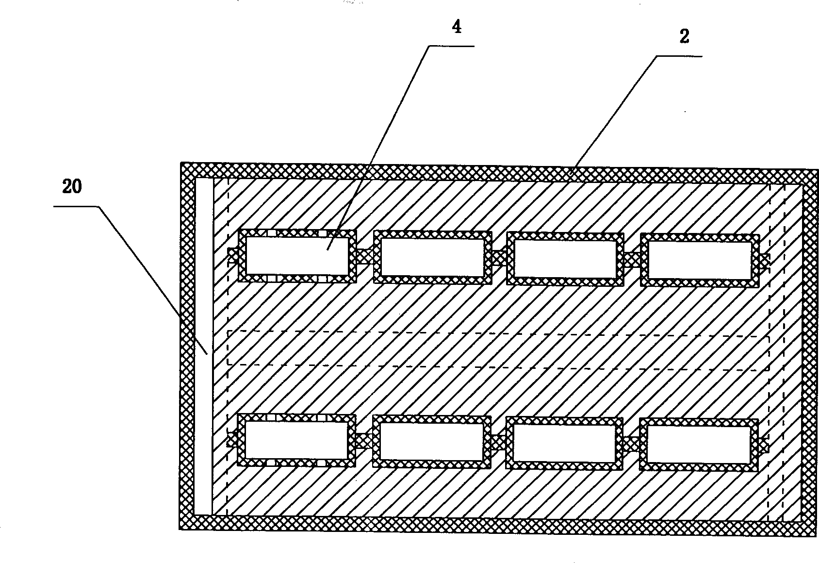
[0020] Embodiment: a specific embodiment of the present invention is such as figure 1 , figure 2 , image 3 , Figure 4 As shown, the furnace has a square furnace body (2), and the furnace body has two layers, the inner layer is an insulating layer (2-1), and the outer layer is a brick layer (2-2). The furnace body is provided with two rows from top to bottom. The lower vertical calcined coal tank (4) is surrounded by fire channels (5). There are two parallel groups of calcined coal tanks (4), eight in total, with a feeding hopper (1) at the top and a discharge hopper at the bottom ( 6), there is a vertical partition wall (10) in the middle of the furnace body (2), which divides the calcined coal tank (4) and the fire channel into two groups on the left and right, and there is a separation wall (17) between each group of calcined coal tanks. , the fire path in the furnace body forms a turn-back fire path from top to bottom through the staggered distribution of the horizont...


PUM


Abstract

A 8-chamber 9-layer high-temp calciner is composed of 8 coal calcining chambers in two rows, heating fire channel surrounding them, flue and chimney. The material feeding hopper and discharging hopper are respectively on the top and bottom of said calcining chambers. Its advantages are long service life, and high temp (1200-1300 deg.C).

Description

technical field [0001] The invention belongs to the structure of an industrial kiln, in particular to an eight-pot nine-layer calciner. Background technique [0002] The carbon calcination furnace currently used in China is a technology introduced from Japan and the former Soviet Union in the 1970s. The furnace type is 6 tanks and 3 layers. After the 1980s, it was changed to 6 tanks and 5 layers. After 1999, it was upgraded to 6 tanks and 9 layers of fire. The physical and chemical indicators of carbon, in the 1970s, the volatile matter could only be calcined to 2%, and the resistivity was 1600 ohms. After the 80s and 90s, the volatile matter could be calcined by 2%. , Since 1995, it has increased to 0.9%-1%, and the resistivity is about 1100 ohms. Compared with the electric calciner, there is still a big gap. Using the electric calciner, the volatile content reaches 0.6%, and the resistivity drops to about 800 ohms. , but the cost of the electric calciner is too high, and ...

Claims


Application Information

Patent Timeline
Patent Type & Authority Applications(China)
IPC IPC(8): F27B5/02
Inventor 李令杰
Owner 李令杰
Learn More