Induction friction welding method

A technology of friction welding and induction welding, applied in welding equipment, high-frequency current welding equipment, non-electric welding equipment, etc., can solve the problems of unsuitable for on-site installation welding, complex mechanical devices, expensive equipment, etc., to avoid solidification cracks, Increased welding cross-sectional area and good welding quality

Inactive Publication Date: 2002-08-28
BEIHANG UNIV
View PDF0 Cites 24 Cited by
  • Summary
  • Abstract
  • Description
  • Claims
  • Application Information

AI Technical Summary

Problems solved by technology

[0009] Although friction welding is one of the main technical methods in the field of welding today and is the most active research hotspot, this friction welding method requires high-power mechanical devices for frictional

Method used


Image

  • Induction friction welding method
  • Induction friction welding method
  • Induction friction welding method

Examples


Embodiment Construction

[0021] The present invention is further described below in conjunction with embodiment and accompanying drawing.

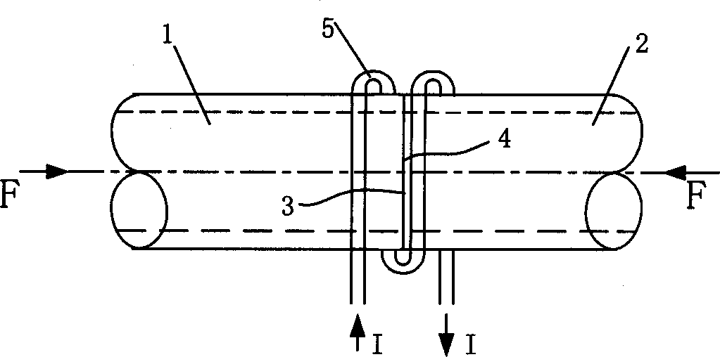
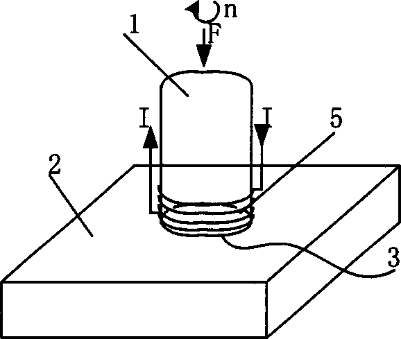
[0022] figure 1 It is a schematic diagram of the rotary induction friction welding method for two tubular members. The end faces 3, 4 of the two tubular members 1, 2 to be welded are the interfaces to be welded. Wind the induction coil 5 at the welding joint, the coil is a flexible high-frequency induction coil, and is cooled by water, the number of winding layers is single or multi-layer, the number of turns is 5-20 turns, and the inner diameter of the coil is 10-30mm larger than the outer diameter of the workpiece . During welding, an alternating current is passed through the induction coil 5, and when the welding interface reaches a predetermined temperature, the pipes 1 and 2 are driven by the headstock to perform relative frictional rotational movement, and the frictional movement removes impurities such as scale on the welding interface etc. Finally, the ...


PUM


Abstract

An induction-friction welding method includes such steps as heating the interfaces to be welded by induction coil, making relative friction between two workpieces to be welded to remove oxide layer obstructing welding, and further axially pressing both workpieces so to form welded joint. Its advantages are high efficiency, and broad spectrum.

Description

(1) Technical field [0001] The invention belongs to a welding method, and is an invention and creation of an induction friction welding method. (2) Technical background [0002] Induction brazing and friction welding are currently the two most important solid phase joining methods. The development and application of friction welding has a history of more than 30 years. The basic method is that one component rubs another component under pressure to generate heat. Once sufficient heat is generated, the frictional motion is terminated, but the pressure can be maintained or increased for a period of time to promote the completion of the weld. [0003] According to the trajectory of the relative frictional motion of the workpiece, friction welding can be divided into: [0004] 1. Rotary friction welding. This is the most common friction welding. It takes the center line of one workpiece as the axis and performs high-speed rotational motion relative to another workpiece. Then...

Claims


Application Information

Patent Timeline
IPC IPC(8): B23K13/01B23K20/12
Inventor 齐铂金吴红杰
Owner BEIHANG UNIV
Why Eureka
Try Eureka