Vortex compressor

A scroll compressor and volute technology, applied in the field of scroll compressors, can solve problems such as decline, increase, and leakage of scroll compressor compression efficiency

Inactive Publication Date: 2002-08-28
MITSUBISHI HEAVY IND LTD
View PDF0 Cites 8 Cited by
  • Summary
  • Abstract
  • Description
  • Claims
  • Application Information

AI Technical Summary

Problems solved by technology

[0013] In other words, when in order to increase the compression ratio V i While increasing L / H, the theoretical efficiency increases; however, in practice, the amount of refrigerant leaking from the compression chamber via the joint portion between the stepped portions 52 and 53 increases due to the high pressure and the increase in the height L
Therefore, there is a problem that the compression efficiency of the scroll compressor decreases due to leakage

Method used


Image

  • Vortex compressor
  • Vortex compressor
  • Vortex compressor

Examples


Embodiment Construction

[0032] Refer to attached figure 1 Through 8, an embodiment of the scroll compressor according to the present invention will be explained.

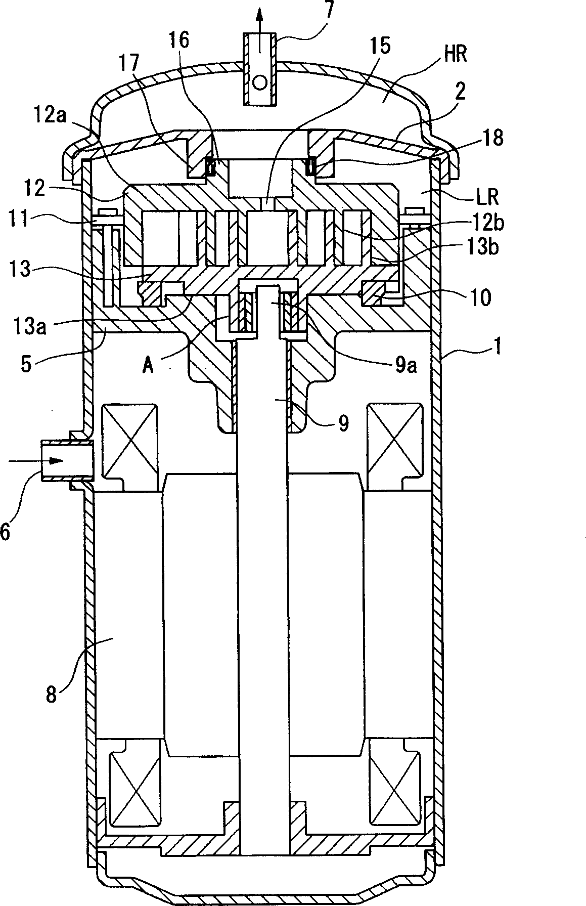
[0033] figure 1 The structure of a back pressure scroll compressor as an embodiment of the present invention is shown. The scroll compressor includes an airtight casing 1, a discharge cover 2 that separates the casing 1 into a high-pressure chamber (HR) and a low-pressure chamber (LR), a frame 5, a suction pipe 6, a discharge pipe 7, a motor 8, and a rotating shaft 9 And anti-rotation mechanism 10.

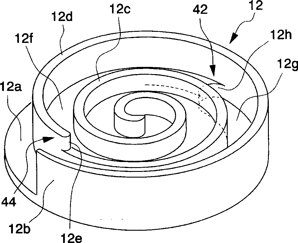
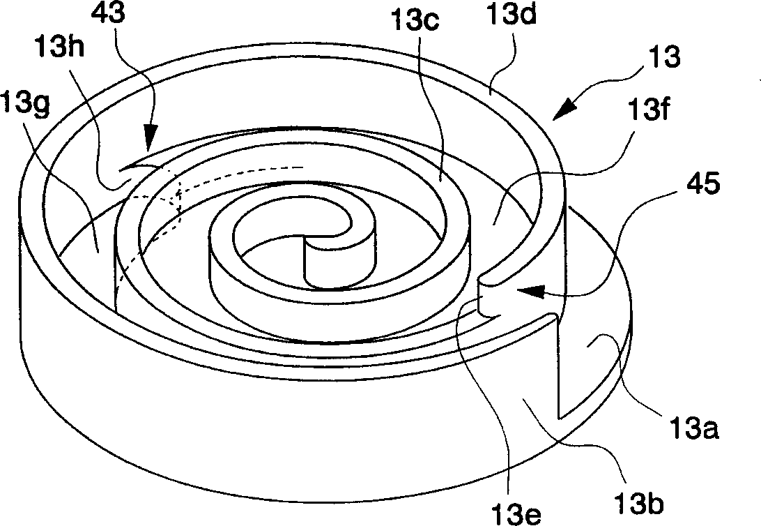
[0034] In addition, the scroll compressor has a fixed scroll 12 and a surrounding scroll 13 engaged with the fixed scroll 12 . Such as figure 2 As shown, the fixed volute 12 includes a spiral wall 12b disposed on the side surface of the end plate 12a. The surrounding volute 13 also includes a spiral wall 13 b disposed on the side surface of the end plate 13 a , especially, the shape of the wall 13 b is similar to that of the wall 12 b ...


PUM


Abstract

The invention discloses a scroll compressor, comprising: a fixed volute fixed in place and having a spiral wall body provided on one side surface of an end plate; and a spiral wall body provided on one side surface of an end plate (13a). A surrounding volute (13) of the wall body (13b), which is supported by the joining of the walls so as to circle and revolve around the fixed volute without rotating. When the length of the wall (13b) outward than the stepped portion (43) provided on the end plate (13a) is represented by H, and the height difference of the stepped portion (43) is represented by L, L/H is 0.2 or smaller.

Description

technical field [0001] The present invention relates to a scroll compressor installed in an air conditioner, a refrigerator, and the like. Background technique [0002] In a traditional scroll compressor, the fixed scroll and the surrounding scroll are arranged by joining their spiral walls, and the fluid in the compression chamber formed between the walls is surrounded by the surrounding scroll due to the volume of the compression chamber. As the fixed volute gradually decreases, it is compressed. [0003] The compression ratio in a scroll compressor design is the maximum volume of the compression chamber (the volume when the compression chamber is formed by the meshing of the walls) to the minimum volume of the compression chamber (just before the walls disengage and the compression chamber disappears). The ratio of the volume) and expressed by the following equation (I): [0004] V i ={A(θ suc )·L} / {A(θ top )·L}=A(θ suc ) / A(θ top ) ............

Claims


Application Information

Patent Timeline
Patent Type & Authority Applications(China)
IPC IPC(8): F04C18/02
CPCF04C18/0276F04C18/02
Inventor 藤田胜博竹内真实伊藤隆英
Owner MITSUBISHI HEAVY IND LTD
Why Eureka
Try Eureka