Improved mass flow sensor interface circuit

A mass flow and circuit technology, which is applied in the direction of measuring flow/mass flow, instruments, measuring devices, etc., can solve problems such as the deterioration of the maximum signal voltage in response to flow, the shunt effect cannot be ignored, and the reduction of output voltage, etc., to increase the overall effect, The effect of reducing the nonlinear effect and increasing the output voltage

Inactive Publication Date: 2002-09-18
米克罗利斯公司
View PDF1 Cites 0 Cited by
  • Summary
  • Abstract
  • Description
  • Claims
  • Application Information

AI Technical Summary

Problems solved by technology

If too many equivalent impedances are in parallel with the sense resistor, they degrade the maximum signal voltage that can be drawn from the sense resistor by the response flow
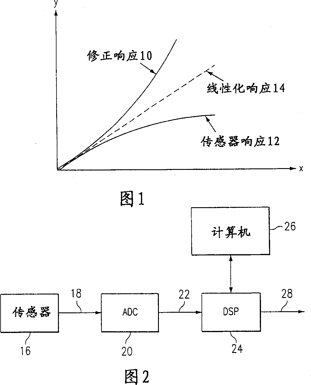
[0006] Second, in prior art circuits, the relationship between the difference between the output voltage (which is proportional to flow) and the upstream and downstream sensing elements is non-linear, which is an undesirable feature of the prior art
However, impedances R1 and R2 are only approximately R U , R D 8 times the value of , so their shunt effect cannot be ignored, and in practice the shunt effect is very large
The shunt effect is a limitation of prior art circuits because it reduces the output voltage e out value of 30

Method used


Image

  • Improved mass flow sensor interface circuit
  • Improved mass flow sensor interface circuit
  • Improved mass flow sensor interface circuit

Examples


Embodiment Construction

[0045] Preferred embodiments of the invention are illustrated in detail in the drawings, like numerals being used to designate like and corresponding parts throughout the several views.

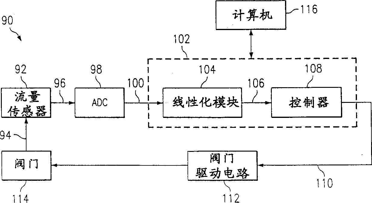
[0046] The present invention provides an improved mass flow detector interface circuit that is more sensitive, simpler and more reliable than any prior art circuit. The mass flow detector interface circuit of the present invention is inherently insensitive to ambient temperature changes and provides an output voltage signal with about twice the sensitivity of prior art circuits. The present invention greatly reduces the non-linear effects present in prior art circuits and improves reliability and accuracy by eliminating the need for manual adjustment and calibration of prior art circuits. Therefore, compared with the prior art circuit, the improved mass flow detector interface circuit of the present invention is simpler, more accurate, more sensitive and more reliable.

[0047] image 3 A br...


PUM


Abstract

The present invention discloses an improved mass flow detector interface ("MFSI") circuit for detecting and measuring the mass flow of a gas and providing an output voltage proportional to said mass flow in a mass flow controller. The mass flow detector interface circuit includes upstream and downstream mass flow detection elements, and an accurate current source for driving the circuit. The circuit also includes an operational amplifier for summing the upstream voltage of the upstream sensing element and the downstream voltage of the downstream sensing element and providing an output signal. A reference voltage source is electrically connected to the positive node of the operational amplifier. The upstream shunt resistor and the downstream shunt resistor share a common node at the negative node of the operational amplifier, and are electrically connected in parallel with the upstream and downstream mass flow detection elements. The mass flow detector interface circuit of the present invention also includes a reference resistor electrically connected between the reference voltage source and the positive node of the operational amplifier, and a feedback resistor electrically connected between the operational amplifier between the positive node and the output. The operational amplifier of the mass flow detector interface circuit provides an output signal proportional to the change in resistance of the upstream and downstream detection elements and thus proportional to the gas mass flow.

Description

technical field [0001] The present invention relates generally to systems and methods for operating a mass flow controller (MFC) and, more particularly, to methods for measuring mass flow within a mass flow controller by sensing a change in the resistance of a sense resistor, or resistance, in response to gas flow systems and methods. Background of the invention [0002] Many manufacturing processes require that the flow of process gases be tightly controlled. For this, the gas mass flow must be detected and determined. The gas mass flow controller senses the mass flow of the gas substantially independently of the gas temperature or pressure, provides a measurement, and meters the gas flow to adjust the mass flow as desired based on the detection and metering. Mass flow controllers operating on the principle of heat transfer are widely used in industry. [0003] A common type of mass flow detector for gases consists of a small diameter tube (capillary) with two coils woun...

Claims


Application Information

Patent Timeline
Patent Type & Authority Applications(China)
IPC IPC(8): G01F1/696
CPCG01F1/696
Inventor 德怀特·S·拉森塔玛斯·I·帕坦尤斯
Owner 米克罗利斯公司
Why Eureka
Try Eureka