Hanging device for floppy disc driver
A disk drive and suspension device technology, applied in the configuration/installation of the recording head, supporting the head, etc., can solve the problems of high overall height, miniaturization restrictions, etc., and achieve the effect of improving flatness, improving precision, and improving vibration characteristics
- Summary
- Abstract
- Description
- Claims
- Application Information
AI Technical Summary
Problems solved by technology
Method used
Image

Examples
no. 2 example
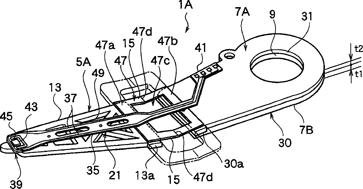
[0076] image 3 , Figure 4 Shows the second embodiment of the present invention. image 3 is a stereogram showing the whole, Figure 4 It is a perspective view showing a semi-finished product and a spring member of the suspension device. Additionally, compared to figure 1 In the suspension device 1 of the embodiment, parts with the same structure are described with the same reference numerals.
[0077] In the present embodiment, the long bottom plate 30 is constituted by the plate 7A having one plate thickness and the other plate 7B having the high-precision hole formed by the above-mentioned etching process. The long bottom plate 30 constitutes a support plate unit in this embodiment. That is, in this embodiment, the structure is such that at least two layers of plates 7A, 7B form the supporting plate means.
[0078] Furthermore, the above-mentioned other plate 7B is made of stainless steel or the like, and in this embodiment, its plate thickness is selected so that, ...
no. 3 example
[0095] Figure 7 ~ Figure 12 A third embodiment of the present invention is shown. Figure 7 is an overall top view of the suspension device 1C, Figure 8 is its enlarged side view, Figure 9 is in Figure 7 The cutaway view of SA-SA, Figure 10 is in Figure 7 The sectional view at SB-SB, Figure 11 is in Figure 7 The enlarged cross-sectional view of SC-SC, Figure 12 It is a process diagram explaining a part of the processing process. Additionally, compared to figure 1 In the suspension device 1 of the first embodiment, corresponding components are described using the same reference numerals.
[0096] like Figure 7 , Figure 8 As shown, the suspension device 1C of this embodiment has a carrier plate 5, a plate 7C integrally formed on the carrier plate 5, and a plate 3A stacked on the one plate 7C and the other plate. The other plate 3A is configured as a long bottom plate, and since it also serves as a bracket arm together with the plate 7C, it is provided lon...
no. 4 example
[0108] Figure 13 represents a fourth embodiment of the present invention, which is image 3 A modification of the second embodiment. Figure 13 It is an overall perspective view of the suspension device 1D. Additionally, with image 3 The corresponding components of the suspension device 1A of the second embodiment are described using the same reference numerals.
[0109] In this embodiment, one plate 7A having a plate thickness capable of forming high-precision holes by the above-mentioned etching process constitutes the long bottom plate 30 together with the other plate 7D. The long bottom plate 30 constitutes the support plate means in this embodiment. The board 7D is composed of a resin layer 7Da and a metal layer 7Db. The resin layer 7Da and the metal layer 7Db have the same structure as the resin layer 3Aa and the metal layer 3Ab of the third embodiment described above. That is, in this embodiment, the support plate device of the suspension device 1D is made into ...
PUM
| Property | Measurement | Unit |
|---|---|---|
| thickness | aaaaa | aaaaa |
Abstract
Description
Claims
Application Information
 - R&D
- Intellectual Property
- Life Sciences
- Materials
- Tech Scout
- Unparalleled Data Quality
- Higher Quality Content
- 60% Fewer Hallucinations
Browse by: Latest US Patents, China's latest patents, Technical Efficacy Thesaurus, Application Domain, Technology Topic, Popular Technical Reports.
© 2025 PatSnap. All rights reserved.Legal|Privacy policy|Modern Slavery Act Transparency Statement|Sitemap|About US| Contact US: help@patsnap.com