Process flow plate with temp. measurement feature

A technology of temperature measurement and flow plate, applied in the direction of temperature measurement of moving fluid, measurement of flow/mass flow, measurement of heat, etc., which can solve maintenance and installation complexity, increase installation and testing time, increase on-site installation time, etc. Problems

Inactive Publication Date: 2002-10-09
ROSEMOUNT INC
View PDF0 Cites 5 Cited by
  • Summary
  • Abstract
  • Description
  • Claims
  • Application Information

AI Technical Summary

Problems solved by technology

Remote temperature measurement requires separate pipe connections, which creates additional maintenance and installation complexity
This added complexity increases field installation time due to increased installation and testing time

Method used


Image

  • Process flow plate with temp. measurement feature
  • Process flow plate with temp. measurement feature
  • Process flow plate with temp. measurement feature

Examples


Embodiment Construction

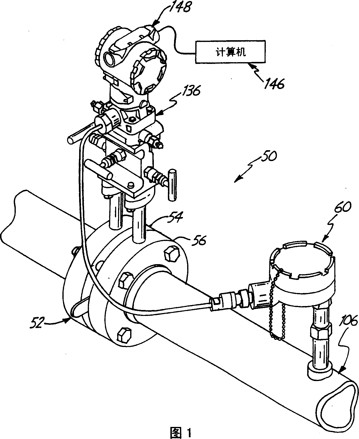
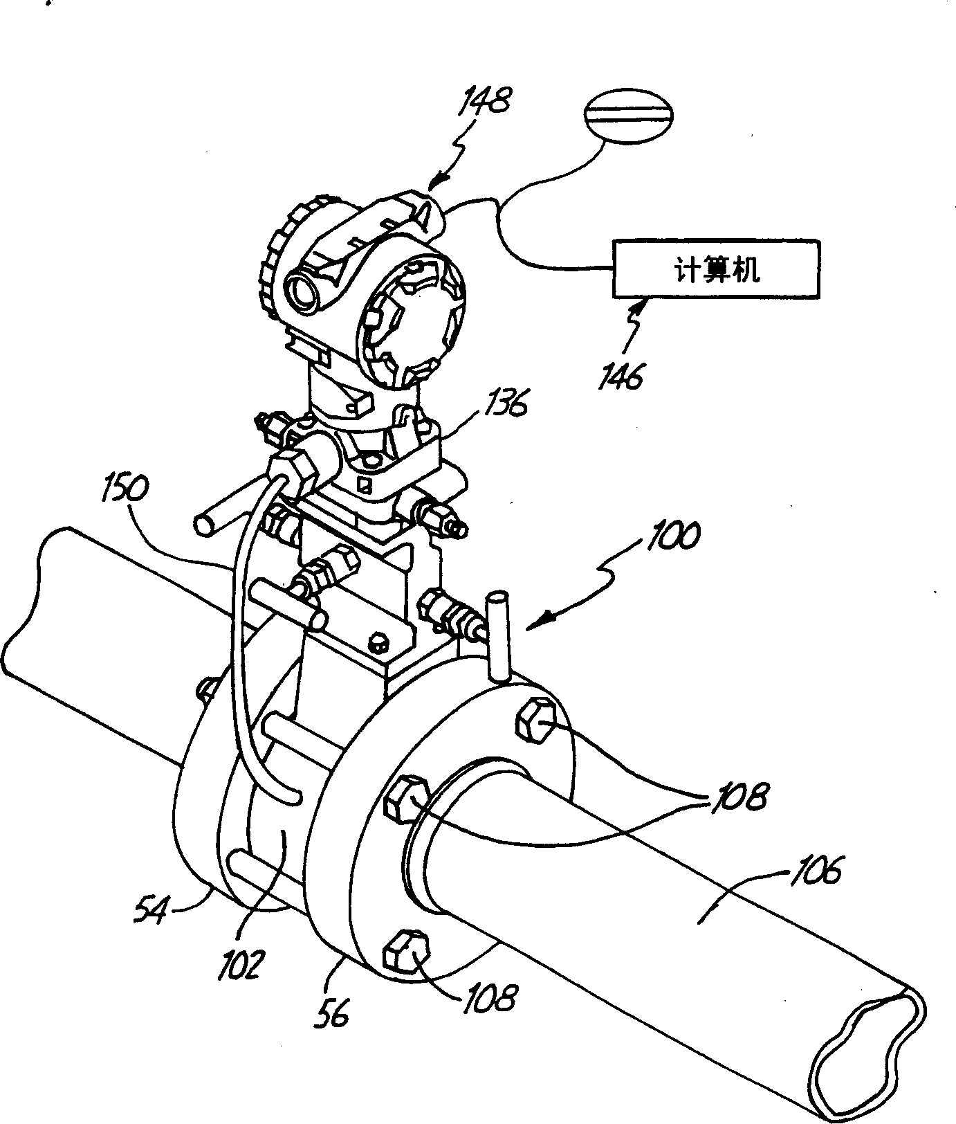
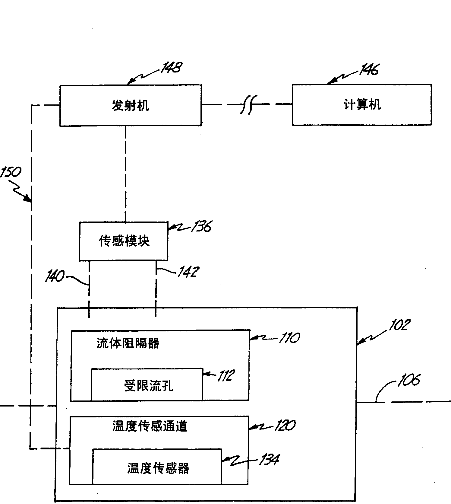
[0029] Figure 2-3 The environment of a flow device 100 including a flow plate 102 with an integral temperature sensor is described. As shown, flow plate 102 may be inserted between tube flanges 54, 56 in fluid channel 106, as figure 2 shown. In the illustrated embodiment, bolts 108 connect flanges 54, 56 to mount flow plate 102 within fluid passages 106 and tubes. Alternative connections may be used to mount flow plate 102 to fluid channel 106, and the application is not limited to the particular connections shown.

[0030] Flow plate 102 includes flow obstructors 110 extending along the perimeter of fluid passages or tubes 106, surrounding restricted flow openings 112, such as image 3 , 5 and 9. exist image 3 , 5 In and 9, the flow plate 102 is an orifice plate with restricted flow holes. An alternative flow obstructor 110 could be a nozzle plate (not shown) with restricted nozzle openings, and the flow obstructor 110 is not limited to an orifice plate. Detailed d...


PUM


Abstract

The differential flow plate (102) is insertable within the fluid channel (106), includes a fluid barrier (110) extending along the outer periphery of the fluid channel (106), forming a restricted fluid opening, and a temperature sensor channel (120) , set near the fluid barrier (110).

Description

technical field [0001] This invention relates to the fluid process measurement and control industry. The process measurement and control industry utilizes process parameter transmitters to remotely monitor parameters of fluids such as slurries, liquids, steam, gases, chemicals, pulp, petroleum, pharmaceuticals, food and other food processing crops. Process parameters include pressure, temperature, flow, water level, turbidity, density, concentration, chemical composition and other properties. Background technique [0002] FIG. 1 depicts a process flow device 50 for measuring process parameters such as pressure and flow. Apparatus 50 includes a flow plate 52 and a remote temperature sensor 60 sandwiched between tube flanges 54 , 56 . The mass flow rate of the liquid stream is a function of the following parameters: Q = KaY F a 2 g c ...

Claims


Application Information

Patent Timeline
Patent Type & Authority Applications(China)
IPC IPC(8): G01F1/00G01F1/36G01F1/42G01F1/50G01F1/88G01F15/02G01K1/14G01K13/02
CPCF16L23/006G01F1/363G01F1/42G01K13/02
Inventor 劳威尔·克莱文
Owner ROSEMOUNT INC
Why Eureka
Try Eureka