Evaluation system of visible deformation as residual welding stress eliminating effect

A residual stress and evaluation system technology, applied in the direction of measuring force, measuring device, instrument, etc., to achieve the effect of improving reliability

Inactive Publication Date: 2002-10-16
XI AN JIAOTONG UNIV
View PDF0 Cites 14 Cited by
  • Summary
  • Abstract
  • Description
  • Claims
  • Application Information

AI Technical Summary

Problems solved by technology

The purpose of the invention is to solve the evaluation problem of welding residual stress relief effect

Method used


Image

  • Evaluation system of visible deformation as residual welding stress eliminating effect

Examples


Embodiment Construction

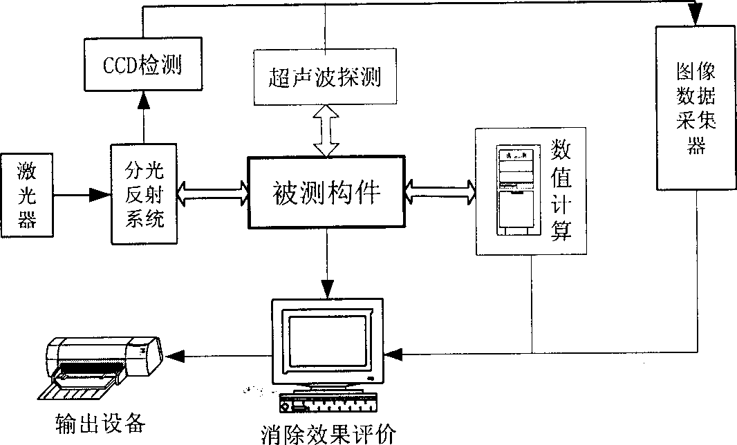
[0015] The present invention will be specifically described below in conjunction with the accompanying drawings.

[0016] figure 1 It is a block diagram representing the system of the present invention. According to the technical scheme of the present invention, three methods for obtaining basic data adopted in the system are:

[0017] 1) Ultrasonic method: use the ultrasonic method to measure the thickness before and after the elimination of residual stress, and study the visible deformation in the thickness direction of the plate caused by the treatment of residual stress. The use of ultrasonic waves to measure thickness dimensions is very mature, and there are many related equipment. The invention adopts the Pan-American 25DL high-precision ultrasonic thickness gauge to measure the thickness with high precision, reliability and good repeatability. At the characteristic points of the stress field, such as the center of the weld, measure the thickness difference before and ...


PUM


Abstract

The evaluation system includes through paths of ultrasonic measurement of plate thickness change before and after eliminating residual stress, laser measurement of position change of some characteristic point or area in welded product and numerical calculation of residual stress eliminating effect and all the data of the three paths are transmitted to the eliminating effect evaluation. The resultobtained through analysis and calculation in the eliminating effect evaluation part is output via the output equipment to complete the evaluation. The present invention has important significance to evaluate the welded product and raise the reliability of important welded structure. Furthermore, it has some reference and application value to similar material and structure.

Description

[0001] 1. Fields: [0002] The invention belongs to material processing engineering, in particular to a visual deformation evaluation system for welding residual stress elimination effect. 2. Background technology [0003] The welding residual stress in the welding products with welding as the main connection method will be gradually released in the subsequent use process, which will directly affect the dimensional stability of the welding products. Therefore, after the welding is completed, it is always necessary to try to relieve the stress of the welded products. The commonly used methods mainly include local or overall heat treatment, vibration, overload, temperature difference stretching and hammering. However, how to evaluate the effect of eliminating welding residual stress is usually determined by direct measurement of residual stress, such as destructive section method, semi-destructive blind hole measurement method and non-destructive X-ray, magnetic and acoustic me...

Claims


Application Information

Patent Timeline
Patent Type & Authority Applications(China)
IPC IPC(8): G01L1/00
Inventor 张建勋裴怡薛勇
Owner XI AN JIAOTONG UNIV
Why Eureka
Try Eureka