Rotary cutting machine

A technology of rotary cutting machine and rolling rod, which is applied in the direction of circular rotary machine, veneer chip manufacturing, wood processing equipment, etc. It can solve the problems of blocking fibers, not being able to be used as the surface of plywood, and difficult to detach.

Inactive Publication Date: 2002-10-23
MEINAN MASCH WORKS INC
View PDF1 Cites 6 Cited by
  • Summary
  • Abstract
  • Description
  • Claims
  • Application Information

AI Technical Summary

Problems solved by technology

[0009] However, in the above-mentioned rotary cutting machine, due to the different types of logs, many small scars will be formed on the surface of the cut veneer, so it cannot be used as a veneer that requires no scars on the surface of the plywood.
[0010] In use Figure 17 to Figure 19 In the case of the roll bar shown above, although the above-mentioned scratches on the surface of the veneer obtained b

Method used


Image

  • Rotary cutting machine
  • Rotary cutting machine
  • Rotary cutting machine

Examples


Embodiment Construction

[0047] Embodiments of the present invention will be described below.

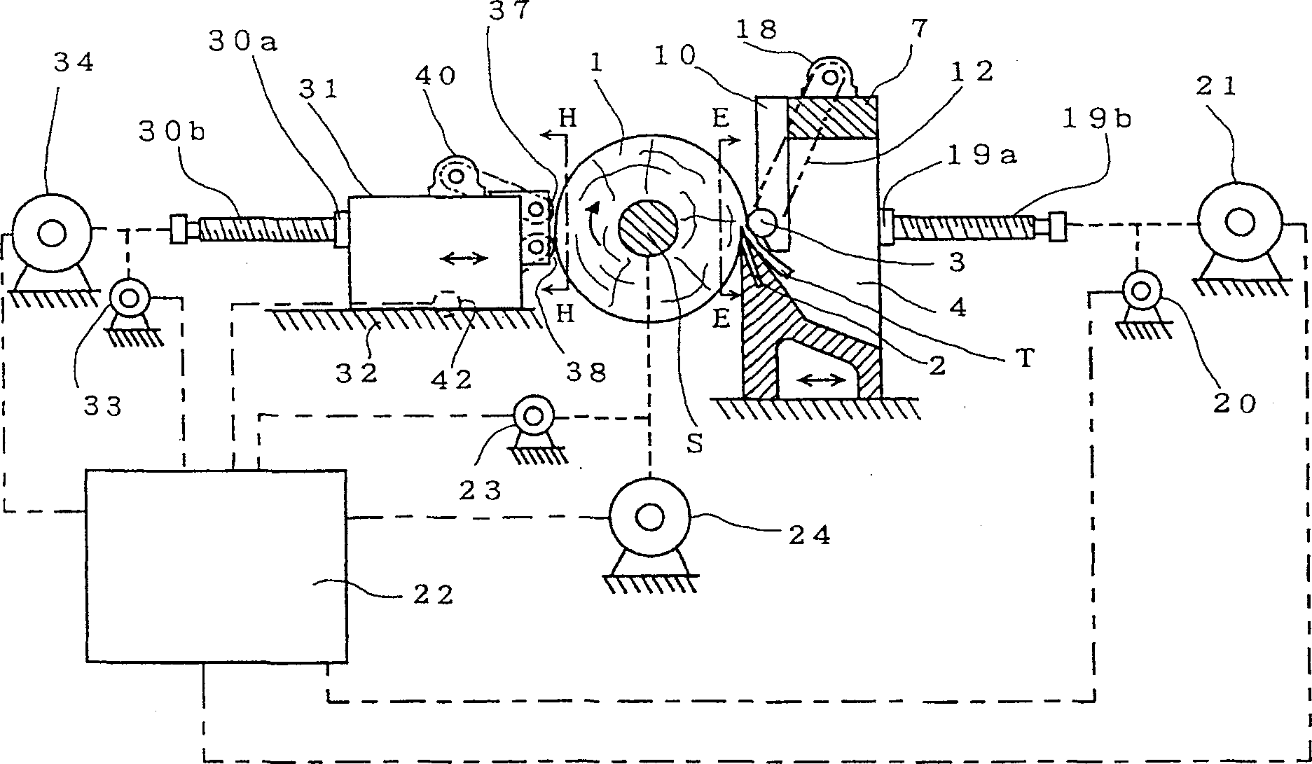
[0048] like figure 1 As shown in the side explanatory diagram, a planer table 4 is arranged on the rotary cutting machine formed, on which a pair of pillars S, a cutter 2 and a rolling bar 3 are arranged, and a pair of pillars S is arranged so that it can move freely in the direction of the axis of the log 1. Advance and retreat, the log 1 is supported by the prop S freely rotating, and the cutter 2 cuts the log 1 .

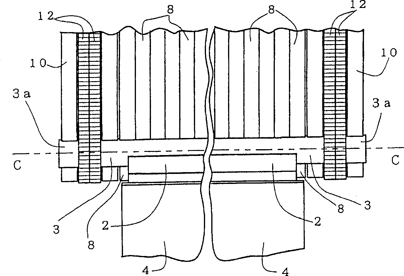
[0049] figure 2 is in figure 1 The front explanatory view with the log 1 removed and a part omitted, viewed from the direction of the dot-dash line E-E arrow; image 3 Yes figure 2 Partial enlargement near the right. by figure 2 and image 3 As shown, the roller bar 3 is arranged parallel to the tip of the tool 2 .

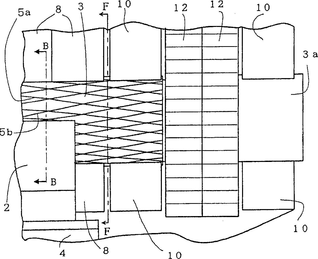
[0050] Figure 4 Yes image 3 Partial front view of the end of middle roll bar 3; Figure 5 From Figure 4 An enlarged explanatory diagram of a partial cross-sectio...


PUM

PropertyMeasurementUnit
Diameteraaaaaaaaaa

Abstract

The invention provides a rotary cutting machine, which can be driven to obtain a cut veneer, and the veneer can be used as a plywood surface without residual scars. The technical solution adopted to solve this technical problem is that the rotary cutting machine drives the tool to pressurize the log peripheral surface at the upstream side of the log rotation direction, and the tool is fixed on the planer table to cut the rotating log; (3) A plurality of grooves are formed on the peripheral surface, and the shape of the grooves (5a) in the section perpendicular to the axis centerline of the roller rod (3) is such that at the upstream side in the direction of rotation of the roller rod, the corner (3e) The angle formed by the tangent of the tangent and the outwardly protruding line (3b) is 130 to 160 degrees, and the angle (3e) is formed by the outer peripheral line (3d) of the rolling bar (3) and the side extending outward from the centerline of the rolling bar (3) shaft. The outgoing line (3b) constitutes.

Description

technical field [0001] The present invention relates to a rotary cutter with roller bars for cutting glued veneers (hereinafter referred to as veneers) from logs. Background technique [0002] The inventors of the present invention previously proposed a rotary cutter described in JP-A-11-99507. [0003] This kind of rotary cutting machine is equipped with: a plurality of convex parts arranged on the peripheral surface of the roller rod and whose height does not protrude from the peripheral surface of the roller rod; sliding bearings, fixed on the planer table and able to keep the free rotation of the roller rod, The shape of the section at the center line of the roller shaft is an arc shape that opens on the side of the log, and is arranged on the opposite side of the log with the roller as the center and opposite to the log; the driving source that rotates the roller held on the sliding bearing . [0004] The roller bar having such a structure can transmit at least a part...

Claims


Application Information

Patent Timeline
IPC IPC(8): B27L5/04B27L5/02
CPCB27L5/025B27L5/04
Inventor 渡边贤藏
Owner MEINAN MASCH WORKS INC
Why Eureka
Try Eureka