Shield digger bit

A technology of roadheader and cutter head, which is applied in the field of cutter head of shield tunneling machine, which can solve the problems of disc cutter configuration restrictions, difficulty in configuring disc cutters, troublesome loading and unloading, etc., shorten construction period, realize miniaturization, and easy operation Effect

Inactive Publication Date: 2002-10-23
KOMATSU LTD
View PDF2 Cites 17 Cited by
  • Summary
  • Abstract
  • Description
  • Claims
  • Application Information

AI Technical Summary

Problems solved by technology

Therefore, there is a problem that the arrangement of disc knives is limited, and it is difficult to arrange disc knives at the corners of the cutter head.
In addition, since the disk knife support member is also enlarged, there is a problem that it is troublesome to replace the disk knife, attach and detach it, etc.
[0010] On the other hand, in the

Method used


Image

  • Shield digger bit
  • Shield digger bit
  • Shield digger bit

Examples


Embodiment Construction

[0022] Specific embodiments of the cutter head of the shield tunneling machine of the present invention will be described below with reference to the accompanying drawings.

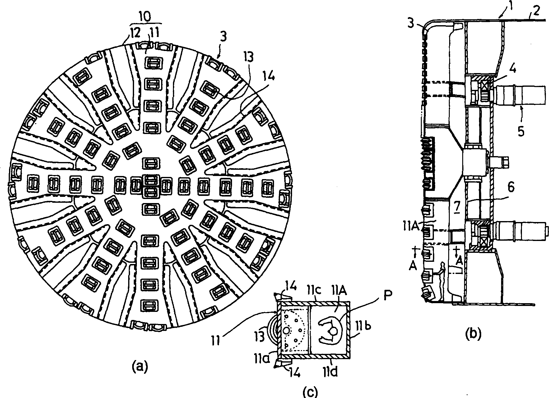
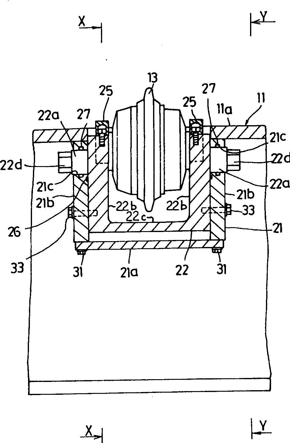
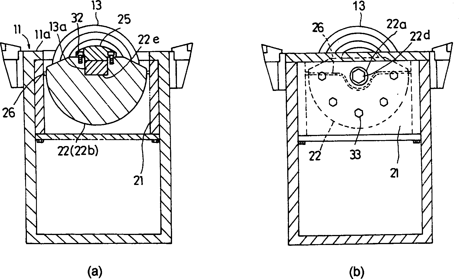
[0023] figure 1 A schematic configuration diagram of a shield tunneling machine according to an embodiment of the present invention is shown in the figure, and the front view (a), the main part longitudinal sectional view (b) and the main part sectional enlarged view of A-A direction in (b) are respectively shown (c). and figure 2 A sectional view of main parts for explaining the rotary support structure of the disc cutter is shown in . and image 3 respectively expressed in figure 2 Sectional view of the main part of the X-X direction (a) and figure 2 The sectional view of the main part of the Y-Y direction in (b). and Figure 4 An explanatory diagram showing the replacement procedure of the disc cutter is shown in .

[0024] The shield tunneling machine 1 of the present embodiment, as figure...


PUM


Abstract

PURPOSE: To provide a cuter head for a shield machine capable of switching a disc cutter between a cutting position and a water cut-off position by means of a compact structure and safely and easily replacing the disc cutter from a cutter head spoke inside without performing any soil improvement for reducing a cost and a construction period. CONSTITUTION: This cutter head is provided with a disc cutter mounting box 21 and a disc cutter cover 22 pivoted to the disc cutter mounting box 21 for supporting the disc cutter rotationally. The bottom part of the disc cutter mounting box 21 is constructed so that it can be freely opened/closed by detaching/ attaching a bolt 31 and can be switched between the cutting position for performing cutting and the water cut-off position for sealing water by means of the disc cutter cover 22 when a pivot shaft 22a is turned. In selection of the water cut-off position, the disc cutter 13 can be replaced from the inside of the cutter head spoke 11.

Description

technical field [0001] The present invention relates to a cutter head of a shield tunneling machine, and more particularly relates to a cutter head capable of easily and safely replacing a disc cutter from the cutter head web. Background technique [0002] In general, a shield boring machine is widely used as an excavating device for constructing various shield tunnels (tunnels for sewers, tunnels for subways, tunnels for communication cables, tunnels for public trenches, etc.) using the shield tunneling method. [0003] In recent years, as a shield tunneling machine suitable for rock plates, hard foundations, and sandy soil, etc., a rotary cutter head is equipped in front of the main body of the roadheader, and the cutter head web or cutter head panel of the cutter head is arranged A shield boring machine in the form of multiple discs and multiple blades. In such a roadheader, excavation of the rock plate portion and the crushed stone portion is particularly carried out by...

Claims


Application Information

Patent Timeline
IPC IPC(8): E21D9/087E21D9/08E21D9/10
CPCE21D9/02E21D9/0692E21D9/087E21D9/11
Inventor 南好人村西正纪
Owner KOMATSU LTD
Why Eureka
Try Eureka