Eureka AIR delivers breakthrough ideas for toughest innovation challenges, trusted by R&D personnel around the world.

Method and equipment for improving image quality

A technology of image quality and equipment, applied in the direction of image communication, using image reproducer of projection device, picture duplicator, etc., can solve the problem of not being able to achieve the improvement effect, and achieve the effect of improving the effect.

Inactive Publication Date: 2002-11-13
NEC DISPLAY SOLUTIONS LTD
View PDF19 Cites 5 Cited by
  • Summary
  • Abstract
  • Description
  • Claims
  • Application Information

AI Technical Summary

Problems solved by technology

If an image with an aspect ratio of 3:4 were to be displayed on a wide screen, the image would be stretched horizontally or both horizontally and vertically, which would not achieve the desired improvement (i.e. flash correction or Craik-O'Brien effect)
If the image with an aspect ratio of 3:4 is to be displayed on a wide screen, it will be expanded nonlinearly. After flash correction, the required improvement effect cannot be achieved by expanding the image (ie correction or Craik-O’Brien effect)

Method used


Image

  • Method and equipment for improving image quality
  • Method and equipment for improving image quality
  • Method and equipment for improving image quality

Examples


no. 2 Embodiment

[0095] Example 2: Use of Illusions

[0096] The Craik-O'Brien effect on vision can be used to improve the visual effect of shape and contrast, and improve image quality.

[0097] The Craik-O'Brien effect represents an optical illusion in which a wide edge placed in an area without any difference in brightness causes the viewer to see the difference in brightness. For example, the Craik-O'Brien effect is described in detail in the Japan Television Society Teohnical Report (November 24, 1977, VVI24-2, pp7-13). The image quality improving apparatus according to the present embodiment improves appearance and contrast visual effects according to the Craik-O'Brien effect. The structure of the image quality improving apparatus according to this embodiment and the first embodiment is substantially the same. The principle and configuration to achieve the Craik-O'Brien effect will be described below.

[0098] Figure 14 A visual effect showing contrast according to the Craik-O'Brien...

no. 3 Embodiment

[0103] Embodiment 3: Compatibility with Widescreen

[0104] Image signals with an aspect ratio of 3:4 can be displayed in several modes on a wide screen with an aspect ratio of 9:16. Figures 17A to 17E Shows several display modes for displaying images on a wide screen. Figure 17A Shows an original image with an aspect ratio of 3:4 to be displayed on a wide screen. Figure 17A The left part of the picture shows a screen with an aspect ratio of 3:4, and the right part shows a wide screen with an aspect ratio of 9:16. Various display modes related to an image having an aspect ratio of 3:4 having a circle at its central portion to be displayed on a wide screen having an aspect ratio of 9:16 are described in detail below by way of example. These display modes include: normal display mode, full display mode, zoom display mode and non-linear display mode. Figure 17B 17C shows the normal display mode and 17C shows the full display mode. Figure 17D shows the variable focus disp...


PUM


Abstract

A device for improving image quality with low cost and small circuit size, having vertical and horizontal low-pass filters (VLPF and HLPF), subtractor, gain adjustment circuit and adder. Among them, the VLPF is used to extract the vertical low frequency component from the input brightness signal; the HLPF is used to extract the horizontal low frequency component from the output signal of the VLPF; the subtractor is used to subtract the output signal of the HLPF from the delay compensated brightness signal; the gain adjustment circuit adjusts The gain of the edge signal produced by the subtractor; the adder adds the gain-adjusted edge signal to the delay-compensated luminance signal. Both VLPF and HLPF include FIR (Finite Impulse Response) filters and IIR (Infinite Impulse Response) filters connected in series or in parallel.

Description

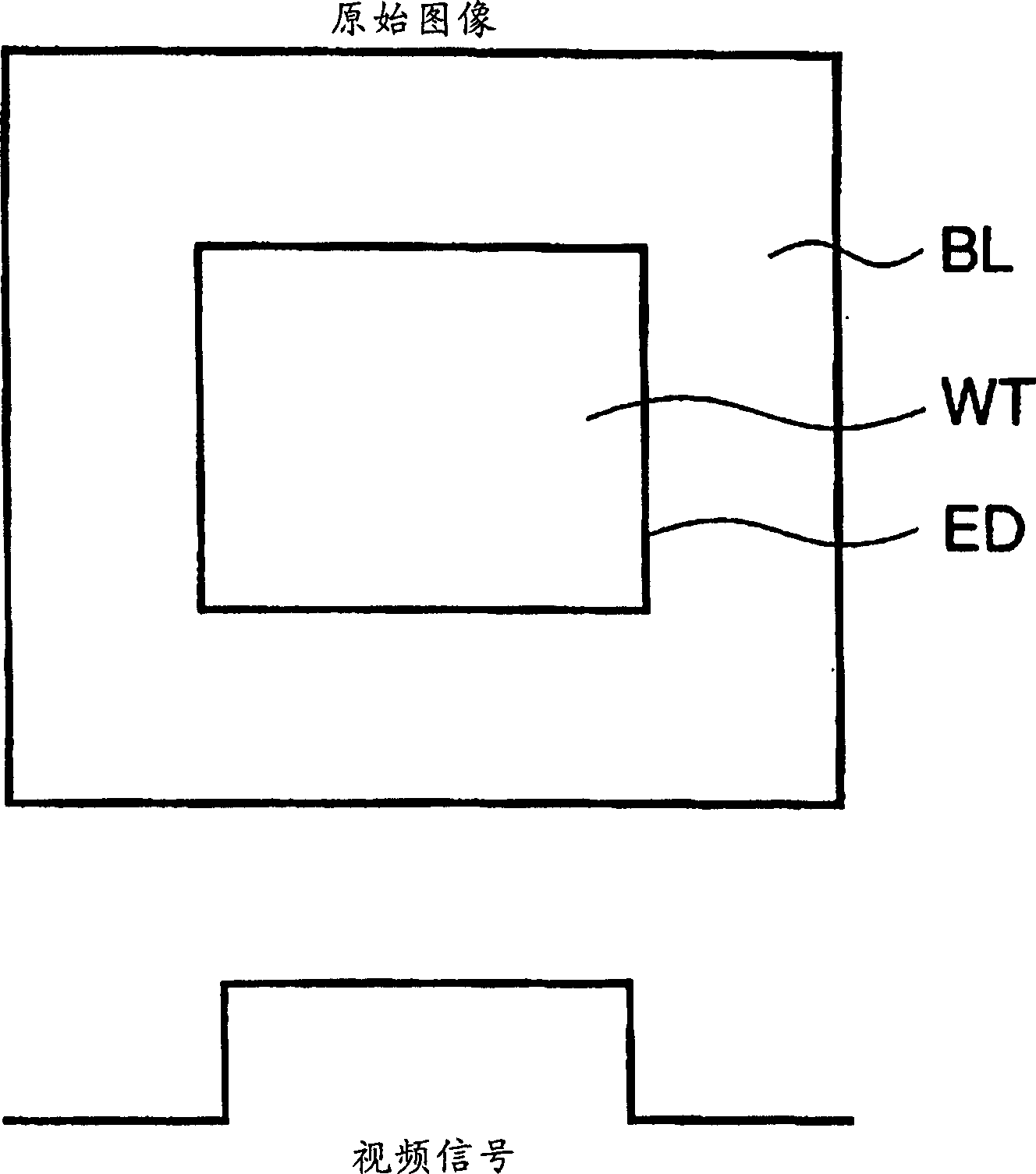
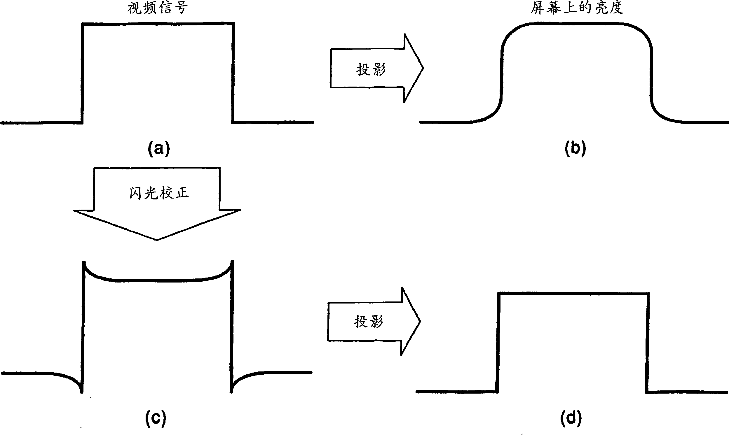
technical field [0001] The present invention relates to methods and devices for improving the quality of images displayed by image display devices such as televisions, video projectors, and the like. Background technique [0002] The image quality displayed by image display devices such as television sets and video projectors in the prior art is deteriorated due to flash. The flash phenomenon is caused by light reflection and scattering in the lens and on the illuminated surface of the projection tube or picture tube, causing light to leak from bright areas to dark areas. The flicker blurs the edges of the displayed image with a large difference in brightness, for example, a large difference in brightness at the border between a white area and a black area. [0003] Figure 1 shows a video projector projecting the original image of the image onto a screen. As shown in FIG. 1 , the central part of the original image has a rectangular white area WT and a black area BL around ...

Claims


Application Information

Patent Timeline
Patent Type & Authority Applications(China)
IPC IPC(8): H04N5/208H04N9/64H04N9/77
CPCH04N5/208H04N7/0122H04N9/646H04N9/77
Inventor 小林巳千男小林玲一
Owner NEC DISPLAY SOLUTIONS LTD
Why Eureka
Eureka Blog
Learn More