Headlight for vehicle

A technology for headlights and vehicles, which is applied in the direction of headlights, vehicle parts, lighting devices, etc., and can solve the problems of thermal deformation of the reflector 4 and thermal deformation of the O-ring 8, and achieve the effect of not being easily thermally deformed and preventing high temperature

Inactive Publication Date: 2002-11-20
KOITO MFG CO LTD
View PDF0 Cites 4 Cited by
  • Summary
  • Abstract
  • Description
  • Claims
  • Application Information

AI Technical Summary

Problems solved by technology

[0005] As a result, the reflector 4 becomes high temperature, and when the reflector 4 adopts the structure of a resin molded product, there is a problem that the reflector 4 is easily thermally deformed.
[0006] Also, when the body support portion 2c of the light source bulb 2 is made of a resin molded product, a structure in which the body support portion 2c of the light source bulb 2 and the inner peripheral surface of the annular wall 4B of the reflector 4 are slidably engaged is adopted in many cases. In this case, there is also a problem that the main body support portion 2c or the O-ring 8 installed for sliding fitting of the main body support portion 2c is prone to thermal deformation.

Method used


Image

  • Headlight for vehicle
  • Headlight for vehicle
  • Headlight for vehicle

Examples


Embodiment Construction

[0033] Embodiments of the present invention will be described below with reference to the drawings.

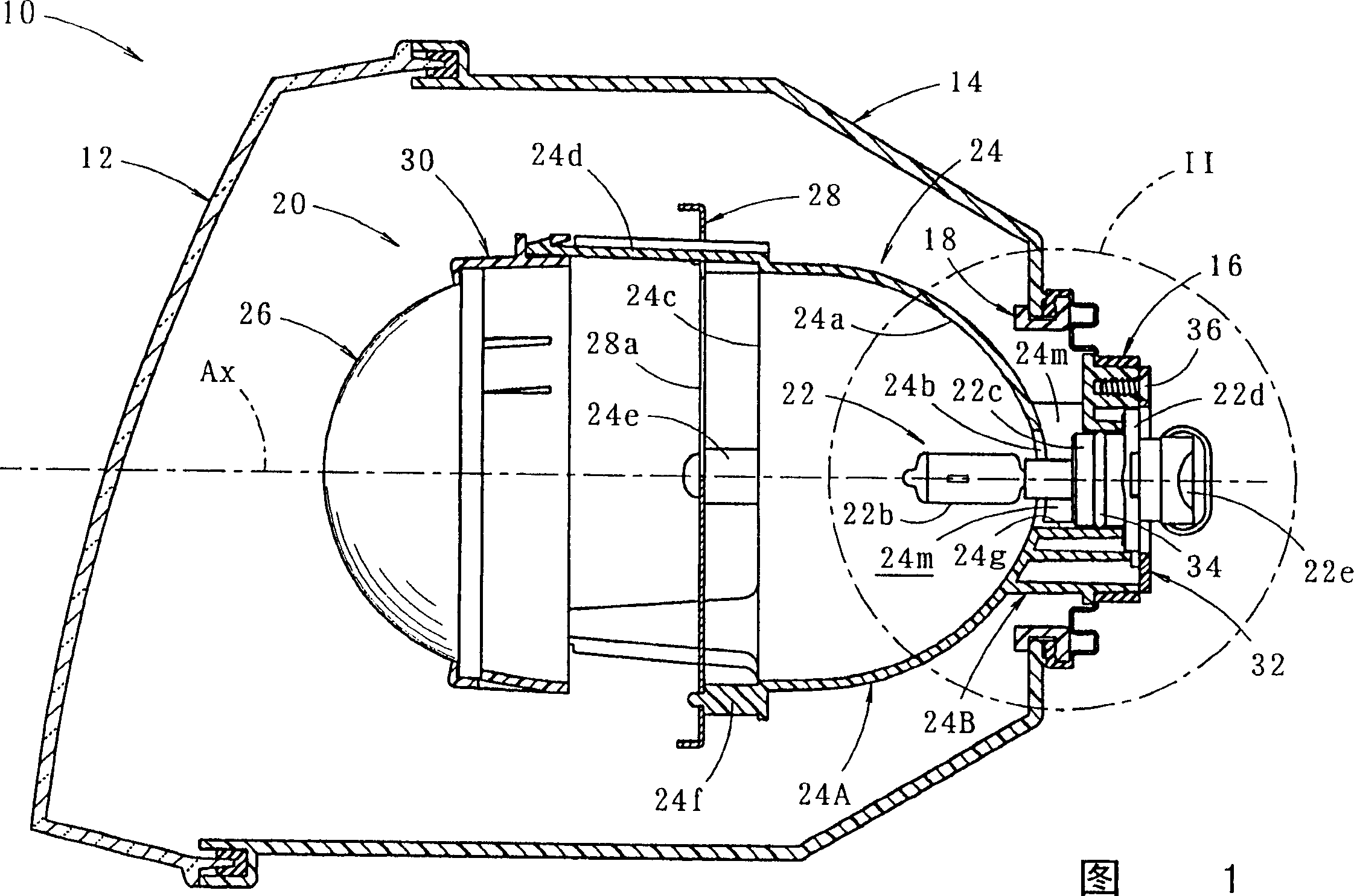
[0034] Fig. 1 is a side sectional view showing a vehicle headlamp according to an embodiment of the present invention.

[0035] As shown in the figure, the vehicle headlamp 10 of this embodiment is housed in a lamp chamber formed by a colorless and transparent cover body 12 and a lamp body 14, and can be tilted vertically and horizontally by an unillustrated aiming mechanism. The lamp assembly 20 in action.

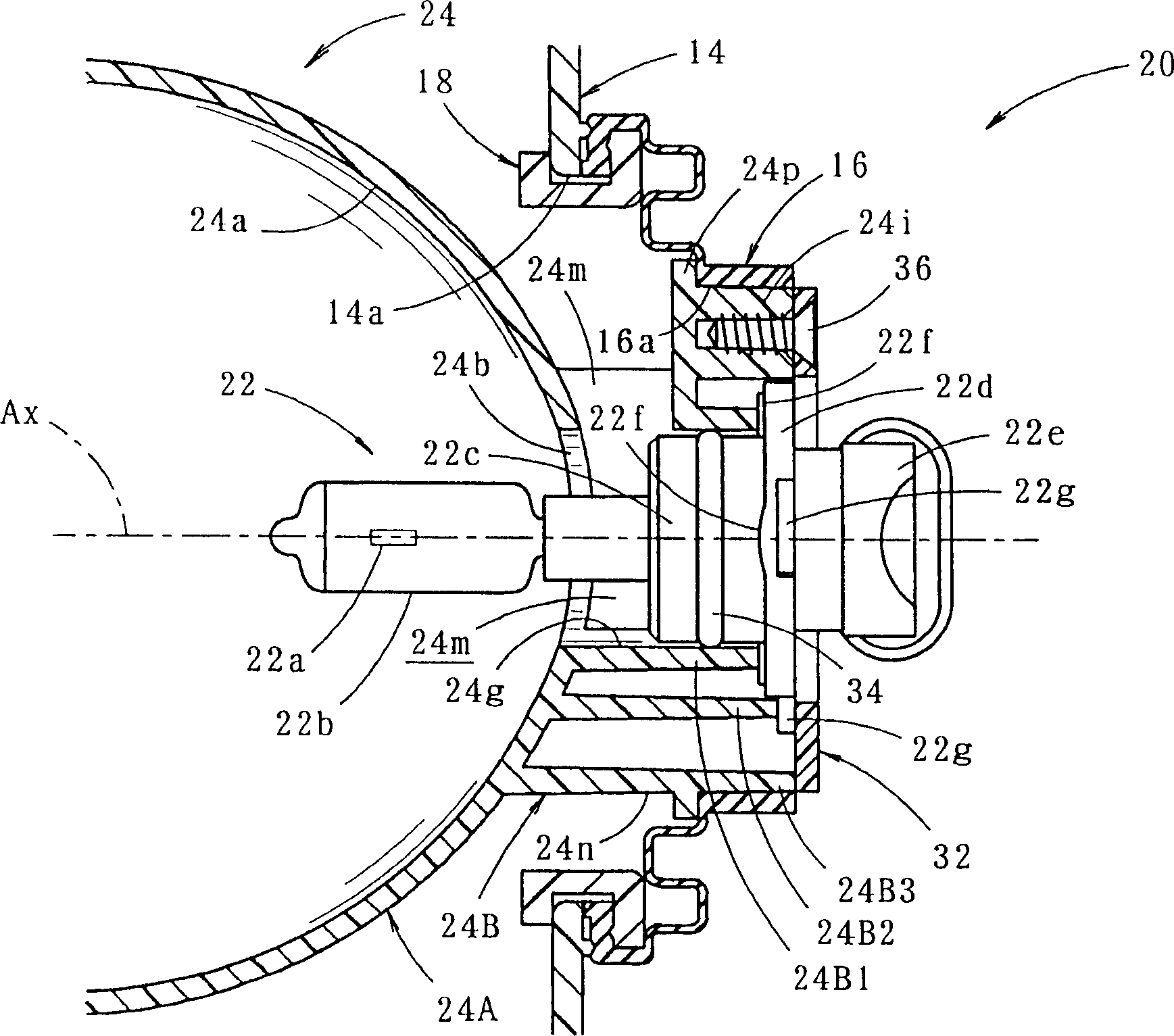
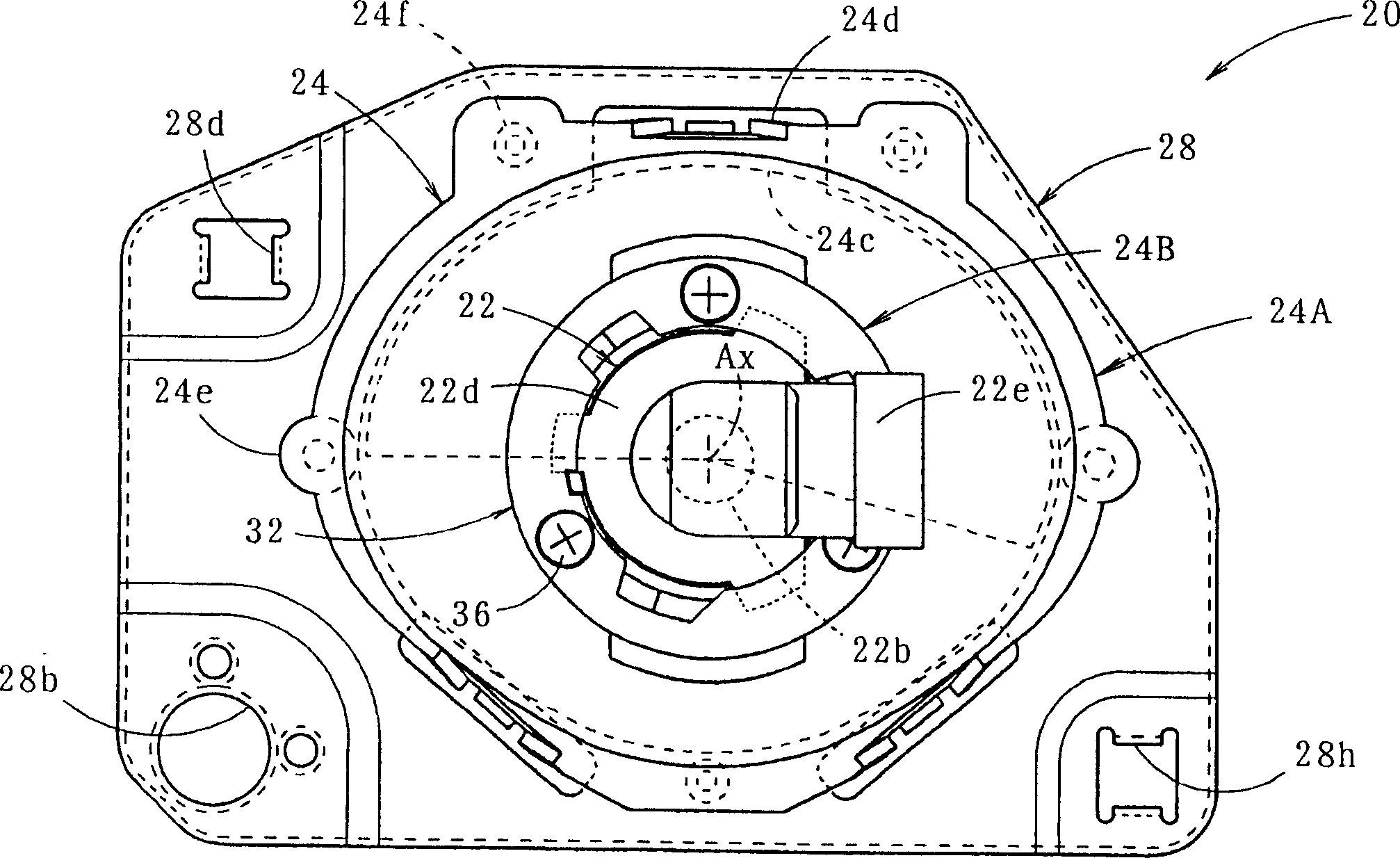
[0036] figure 2 It is a detailed diagram of Part II of Fig. 1, image 3 It is a rear view showing the lamp assembly 20 in a single form.

[0037] As shown in these figures, the lamp unit 20 is a so-called concentrating lamp unit, and includes a light source bulb 22 , a reflector 24 , a projection lens 26 , a shutter 28 , a lens holder 30 , and a bulb holder 32 .

[0038] The light source bulb 22 is a so-called HB4 type tungsten iodine lamp. That is, the light source...


PUM


Abstract

A headlamp for vehicles, wherein a body support portion (22c) of a light source bulb (22) is slidingly engaged with an inner peripheral surface of an annular wall (24B) of a reflector (24), and the flange portion (24d) ) abuts against the rear end surface of the annular wall (24B), and in this state, the flange portion (24d) is clamped from the front and rear sides by the annular wall (24B) and the light bulb fixing member (32), thereby placing the light source The bulb (22) is fixed on the reflector (24). Three cutout holes (24m) penetrating through the annular wall (24B) are formed in front of the sliding engagement position between the annular wall (24B) and the body support portion (22c) of the light source bulb (22). The inner space of the reflecting mirror (24) is communicated with the outer space through these cutout holes (24m), and the heat inside the reflecting mirror (24) is dissipated to the outside, which can prevent the high temperature of the reflecting mirror and reduce the possibility of thermal deformation of the reflecting mirror, etc. sex.

Description

technical field [0001] The present invention relates to a vehicle headlamp, in particular to the structure around the fixing part of the light source bulb on the reflector. Background technique [0002] Generally, in vehicle headlamps, the light source bulb is fixed on the reflector by a bulb fixing member. And, as its specific structure, for example, known Figure 7 structure shown. [0003] In the vehicle headlamp shown in the figure, the light source bulb 2 has a flange portion 2d formed on the peripheral surface of a body support portion 2c that supports the bulb body 2b. On the other hand, the reflector 4 is formed on its reflector body 4A with a bulb insertion hole 4b for inserting the bulb body 2b of the light source bulb 2, and is formed around the bulb insertion hole 4b on the reflector body 4A to protrude backward. The annular wall 4B. And, the main body support portion 2c of the light source bulb 2 is slidably engaged with the inner peripheral surface of the an...

Claims


Application Information

Patent Timeline
Patent Type & Authority Applications(China)
IPC IPC(8): F21S8/10B60Q1/00F21V19/00F21V29/00F21V31/03F21W101/10F21Y101/00
CPCB60Q1/007F21S41/192F21S41/194F21S45/33
Inventor 山本薰
Owner KOITO MFG CO LTD
Why Eureka
Try Eureka