Air condtiioner control system and control method thereof

A technology for control systems and air conditioners, which is applied in air conditioning systems, heating and ventilation control systems, heating and ventilation safety systems, etc., and can solve problems such as long pipelines and compressors that cannot be directly used in air conditioning systems

Inactive Publication Date: 2002-11-20
SAMSUNG ELECTRONICS CO LTD
View PDF2 Cites 21 Cited by
  • Summary
  • Abstract
  • Description
  • Claims
  • Application Information

AI Technical Summary

Problems solved by technology

Therefore, these compressors cannot be directly applied to the air-conditioning system of buildings, because buildin

Method used


Image

  • Air condtiioner control system and control method thereof
  • Air condtiioner control system and control method thereof
  • Air condtiioner control system and control method thereof

Examples


Embodiment Construction

[0025] Exemplary embodiments according to the principles of the present invention are described below with reference to the accompanying drawings.

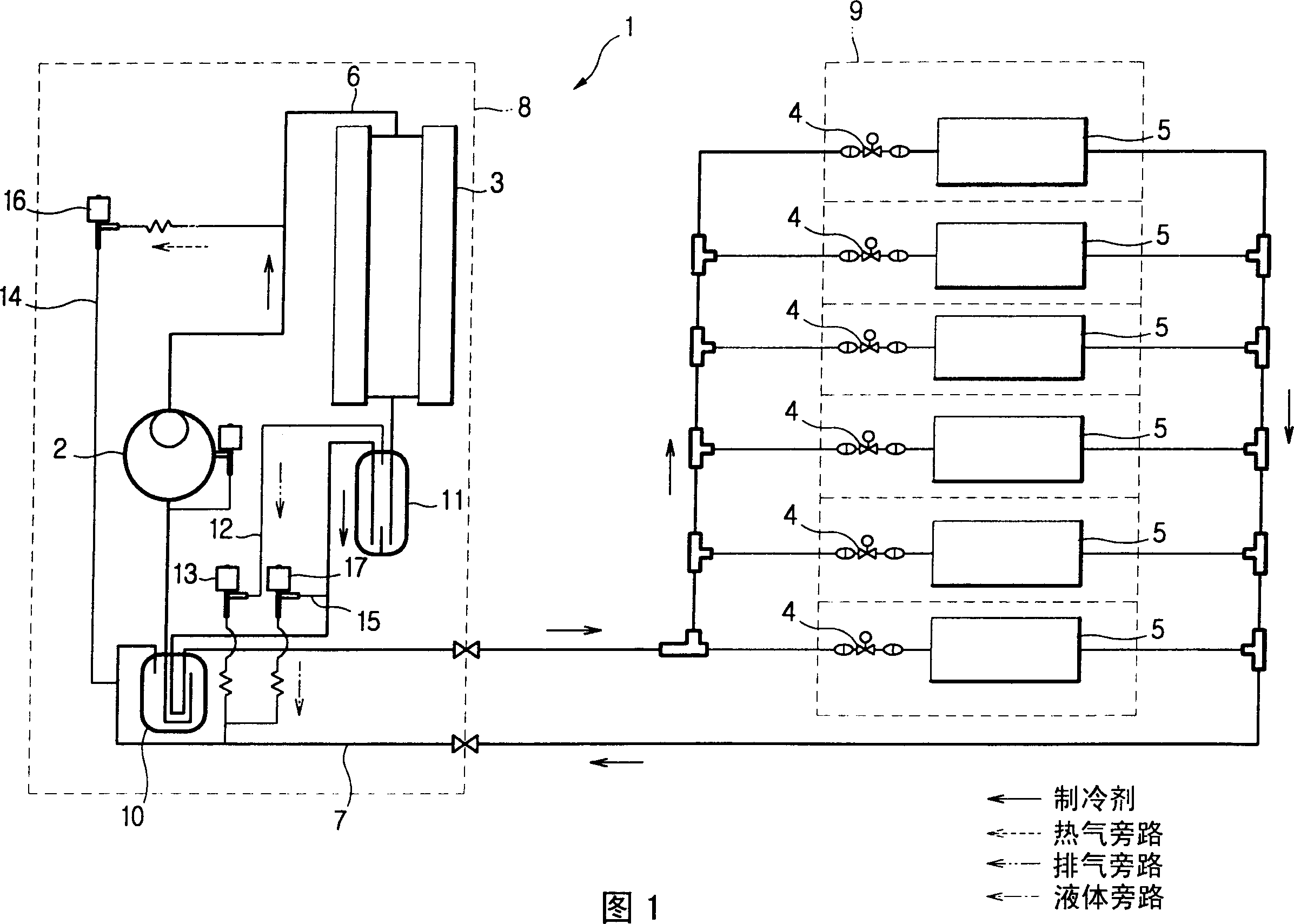
[0026] FIG. 1 is a schematic diagram of a refrigeration cycle of an air conditioner control system according to the present invention.

[0027] The air conditioner 1 of the present invention includes a compressor 2, a condenser 3, a plurality of electric expansion valves 4, and a plurality of evaporators 5, and the evaporators are connected to each other through refrigerant pipelines to form a closed circuit. Of these refrigerant pipes, the refrigerant pipe that connects the outflow side of the compressor 2 to the inflow side of the electric expansion valve 4 is a high-pressure pipe 6 that guides the flow of high-pressure refrigerant discharged from the The refrigerant pipe connecting the outflow side of the valve 4 to the inflow side of the compressor 2 is a low-pressure pipe 7 for guiding the flow of low-pressure refrigerant exp...


PUM


Abstract

An air conditioner control system includes an outdoor unit having a compressor controlled by pulse width modulation, and a plurality of indoor units. Each of the plurality of indoor units has an indoor control unit that calculates the respective required individual cooling capacity, and an indoor communication circuit unit through which the calculated required individual cooling capacity is transmitted. The outdoor unit has an outdoor control unit that generates a duty cycle control signal to control the capacity of the compressor in response to a desired individual cooling capacity sent from the indoor unit; and an outdoor control unit that communicates with an indoor communication circuit unit of a corresponding indoor unit of the plurality of indoor units. The communication circuit unit, each of the plurality of indoor units, calculates the required individual cooling capacity based on at least one of the available cooling capacity of the corresponding unit itself of the plurality of indoor units and the temperature difference between the detected indoor air temperature and a preset temperature. cooling capacity.

Description

technical field [0001] The invention relates to an air conditioner, in particular to an air conditioner control system using a pulse width modulation compressor and a control method thereof. Background technique [0002] An air conditioner provides conditioned air by means of a refrigerant cycle to control characteristics of the air such as room temperature and humidity of houses and buildings. As the indoor conditions desired by people living and working in these houses and buildings differ from each other, and as the outdoor environment changes, the required cooling capacity also often changes. In a multiple air unit conditioner with multiple outdoor cooling units connected to a single outdoor unit, the indoor cooling units differ from each other in the required cooling capacity. In most cases, the total cooling capacity obtained by adding the required cooling capacity of all indoor units tends to vary widely and unpredictably since the individual indoor units can operate...

Claims


Application Information

Patent Timeline
IPC IPC(8): F24F11/02F24F3/06F24F11/00F25B49/02
CPCF24F3/065F25B49/022F25B2600/0261F25B2600/2521F24F11/83F24F11/84
Inventor 文重基金荣晚文济明李庭泯金钟烨赵日镛
Owner SAMSUNG ELECTRONICS CO LTD
Why Eureka
Try Eureka