Pump and its mfg. method

A manufacturing method and technology of a pump chamber, which are applied in the directions of pumps, pump components, variable displacement pump components, etc., can solve the problem that the upper frame body cannot be designed extremely thin, the flow path 53 is not easily formed, and the pump body processing qualification rate is low, etc. problem, to achieve the effect of good material utilization, air tightness, and high positioning accuracy

Inactive Publication Date: 2002-12-04
MATSUSHITA ELECTRIC WORKS LTD
View PDF2 Cites 20 Cited by
  • Summary
  • Abstract
  • Description
  • Claims
  • Application Information

AI Technical Summary

Problems solved by technology

[0004] However, in the example of the above-mentioned prior art, in order to ensure airtightness, it is necessary to fully ensure the overall flatness and parallelism of the mating surfaces of the upper and lower frames 50, 51, and it is difficult to align the upper frame 50 and the lower frame. Simultaneous positioning of the frame body 51 and the valve plate 52 on three layers
Moreover, when the check valve is formed by sandwiching the valve plate 52 between the upper frame body 50 and the lower frame body 51, the processing yield of the pump main body is low when the positioning accuracy is low.
Furthermore, in order to ensure airtightness, along the flow path 53 such as Figure 47 As shown, laser welding is performed on the mating surfaces of the upper and lower frames 50, 51 (symbol 56 is the welded part), and air leakage between the valve plate 52 in the flow path 53 and the upper frame 50 is inevitable. , there is a problem that the compression efficiency deteriorates
Moreover, the formation of the flow path 53 itself is not easy
[0005] Moreover, in the pump disclosed in JP-A-59-200081, since a detection valve is used, a certain thickness must be provided in order to install the detection valve in the upper frame, and the upper frame cannot be designed extremely thin question

Method used


Image

  • Pump and its mfg. method
  • Pump and its mfg. method
  • Pump and its mfg. method

Examples


Embodiment 1

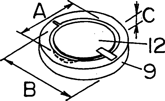
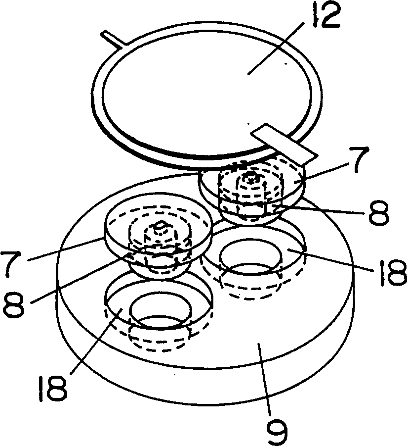
[0112] figure 1 4 shows a diaphragm type pump, which is composed of a disc-shaped diaphragm 12 , a disc-shaped case 9 and a check valve unit 8 . The diaphragm 12 is placed on the upper surface of the case body 9 , and the periphery of the diaphragm 12 is fixed by welding or bonding on the upper surface of the case body 9 , and the pump chamber 1 is formed between the diaphragm 12 and the upper surface of the case body 9 .

[0113] The size of the pump, for example, the outer diameter A of the vibrating membrane 12 is φ20mm, the outer diameter B of the box body 9 is φ22mm, and the height C is 3mm.

[0114] In the case body 9 , a suction side flow path 2 that sucks into the pump chamber 1 and a discharge side flow path 3 that discharges from the pump chamber 1 are formed along the thickness direction of the case body 9 . A check valve accommodating portion 18 is provided between the pump chamber 1 and the flow paths 2 and 3 , and the check valve unit 8 is accommodated and moun...

Embodiment 2

[0122] Figure 5A and Figure 5B This shows an embodiment in which the fluid suction side check valve unit 8 and the fluid discharge side check valve unit 8 have the same shape, and the check valve unit 8 is installed in the case body 9 up and down on the suction side and the discharge side.

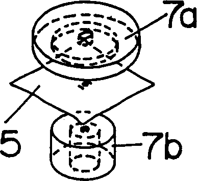
[0123] As in the first embodiment, the check valve frame 7 is formed by the first spacer 7a and the second spacer 7b, but in this embodiment, the first spacer 7a and the second spacer 7b are formed to have the same thickness , Disc shape with the same outer diameter. A check valve membrane 5 is installed between the first spacer 7a and the second spacer 7b, and the check valve membrane 5 is provided as a bendable large-diameter space 19 on the first spacer 7a. Furthermore, the check valve unit 8 is mounted on the suction side so that the first spacer 7a side is formed on the pump chamber 1 side, and the check valve unit 8 is mounted on the discharge side so that the second spacer 7b is...

Embodiment 3

[0126] Figure 6A and Figure 6B An example is shown in which the check valve unit 8 is installed in the case 9 from the side opposite to the installation surface of the diaphragm 12 .

[0127] like Figure 6A and Figure 6B As shown, the check valve housing 7 is formed of a first spacer 7a, a second spacer 7b, and a third spacer 7c. The third spacer 7c is made of PC resin like the first spacer 7a and the second spacer 7b.

[0128] A check valve film 5 is installed between the first spacer 7a and the second spacer 7b, and a flexible space 19 for the check valve film 5 is provided on the side of the first spacer 7a in the suction side check valve unit 8, A flexible space 19 for the check valve diaphragm 5 is provided on the side of the second spacer 7 b in the check valve unit 8 on the discharge side.

[0129] In this embodiment, since the check valve unit 8 is inserted from the side opposite to the installation surface of the vibrating film 12 of the case body 9, and inst...


PUM


Abstract

A pump and its manufacturing method, the pump has a pump chamber (1), suction-side and discharge-side flow paths (2) and (3) communicating with the pump chamber (1), the pump chamber (1) and the flow path A check valve unit (8) is arranged between (2) and (3). The check valve unit (8) is connected by a check valve membrane (5) formed by a thin film and a check valve frame (7) with a pipeline (6) passing through a pressure difference switch using the check valve membrane (5). ) is unitized. The pump has a compact structure, is easy to manufacture, and has high efficiency and reliability.

Description

technical field [0001] The present invention relates to a small pump used in a sphygmomanometer and the like, and particularly relates to the structure of a piezoelectric pump utilizing the action of a piezoelectric actuator. Background technique [0002] Conventionally, such a pump has been disclosed in JP-A-59-200081 and US Patent No. 6,033,191. [0003] Figure 46 It shows the pump disclosed in US Pat. No. 6,033,191, in which a valve plate 52 is sandwiched between an upper frame 50 and a lower frame 51 to form a stack, and a suction side and a discharge side flow path 53 are formed on the upper surface of the lower frame 51 . A vibrating membrane 54 vibrated by a piezoelectric actuator is installed in the upper housing 50 , and a pump chamber is formed between the vibrating membrane 54 and the upper surface of the upper housing 50 . The flow path 53 in the pump chamber and the suction side and the discharge side are communicated through the through hole 55 of the upper f...

Claims


Application Information

Patent Timeline
Patent Type & Authority Applications(China)
IPC IPC(8): F04B43/00F04B43/04F04B53/10
CPCF04B43/046F04B53/1062F04B43/00
Inventor 浦野洋二川口达治北原治伦
Owner MATSUSHITA ELECTRIC WORKS LTD
Why Eureka
Try Eureka