
Microconcave digital controlled laser formation method and device on working surface of friction pair

A working surface, CNC laser technology, used in laser welding equipment, manufacturing tools, metal processing equipment, etc., can solve the problems of unsuitable processing of high-hardness materials, insignificant, increased friction pair life, etc., and achieve significant economic and social benefits. Benefit, improve wear resistance, ensure consistent effect

Inactive Publication Date: 2002-12-18
杭州电子工业学院
View PDF0 Cites 10 Cited by
  • Summary
  • Abstract
  • Description
  • Claims
  • Application Information

AI Technical Summary

Problems solved by technology

However, since the mesh grooves communicate with each other, the lubricating oil stored in the grooves will be squeezed out along the grooves, and the life of the friction pair is not significantly improved.
Vibration impact method can form mutually independent micropits on the working surface of the friction pair, but the wear of the tool head has a certain influence on the depth of the micropits, and it is not suitable for processing high hardness materials

Method used


Image

  • Microconcave digital controlled laser formation method and device on working surface of friction pair
  • Microconcave digital controlled laser formation method and device on working surface of friction pair
  • Microconcave digital controlled laser formation method and device on working surface of friction pair

Examples


Embodiment Construction

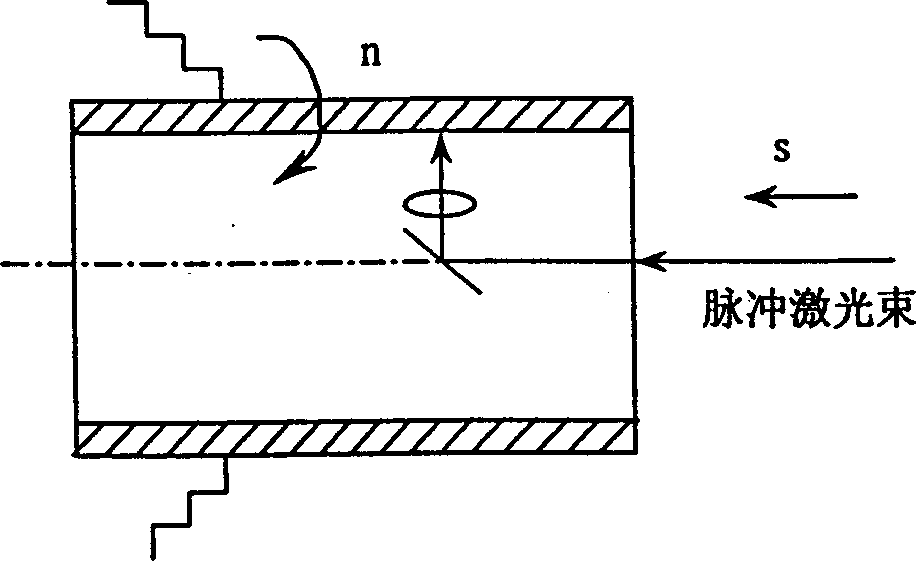
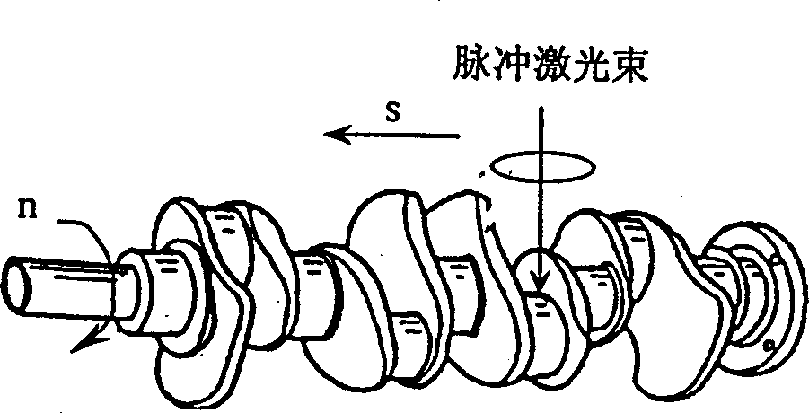
[0019] The micropit CNC laser forming device on the working surface of the friction pair is that the motor 1 drives the laser spindle 5 to perform linear motion through the pinion 2, the big gear 3 and the ball screw 4; the motor 13 drives the transmission shaft 17 to rotate through the pinion 15 and the big gear 14, The small gear 12 and the large gear 11 transmit the rotation of the transmission shaft 17 to the transmission shaft 10, driving the rotation of the workbench 9; the fixture 8 is installed on the workbench 9, and the cylinder 27 is installed in the fixture 8; the numerical control system controls the motor 1, the motor 13 to control the movement speed of the laser spindle 5 and the workbench 9.

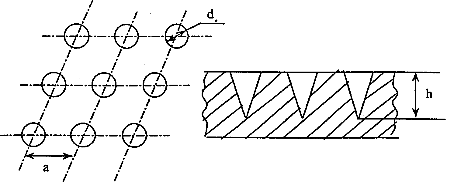
[0020] Such as figure 1 As shown, the relationship between the working parameters of the machine tool and the parameters of the micropit of the cylinder liner is determined by the following relationship: a = π ...


PUM


Abstract

The present invention discloses a micropit numerical control laser forming method on the working surface of friction pair, and is characterized by that the components of the friction pair are rotated, the pulse laser bean can be used and relatively moved along the rotated components of the friction pair, then the focused pulse laser-bean can be used for making micropits on the working surface of friction pair components. Said invention possesses the following advantages: 1. can form micropits with thousands which are mutually independent and identical in depth on the working surface of frictino pair; 2. contactless processing, energy of laser beam and its movement can be regulated, and the rotating speed of components of friction pair also can be regulated; 3. it does not result in deformation of workpiece.

Description

technical field [0001] The invention relates to a surface processing method and a device, in particular to a numerically controlled laser forming method and a device for micropits on the working surface of a friction pair. Background technique [0002] In various friction pairs with relative motion, the working surface of the friction pair must form an oil storage structure to store lubricating oil, reduce friction and wear, and ensure the life of the motion pair. Flat-top honing and superfinishing are usually used as the final processing of the working surface of the friction pair to form a cross-groove flat-top oil storage structure; Carry out reverse electrolysis, form a network groove oil storage structure on the surface, and then honing process; or use vibration and impact processing to form mutually independent micro pits on the working surface of the friction pair, and then honing process. [0003] Both flat top honing and chrome plating of ...

Claims


Application Information

Patent Timeline
Patent Type & Authority Applications(China)
IPC IPC(8): B23K26/36
Inventor 张云电
Owner 杭州电子工业学院
Learn More