Photoelectric temp. monitor

A monitoring device, photoelectric technology, applied in the direction of measuring devices, thermometers, thermometers based on the expansion/contraction of materials, etc., can solve the problems of limited accuracy of temperature measurement, complex structure, etc. The effect of temperature measurement response time

Inactive Publication Date: 2002-12-18
符建
View PDF1 Cites 4 Cited by
  • Summary
  • Abstract
  • Description
  • Claims
  • Application Information

AI Technical Summary

Problems solved by technology

However, the device needs to be equipped with a series of receivers, and the structure is relatively complicated; and the accuracy of temperature measurement is limited by the number of receivers, and it can only measure the temperature measurement point with high precision in a small temperature range

Method used


Image

  • Photoelectric temp. monitor
  • Photoelectric temp. monitor
  • Photoelectric temp. monitor

Examples


example 1

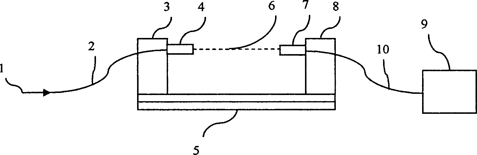
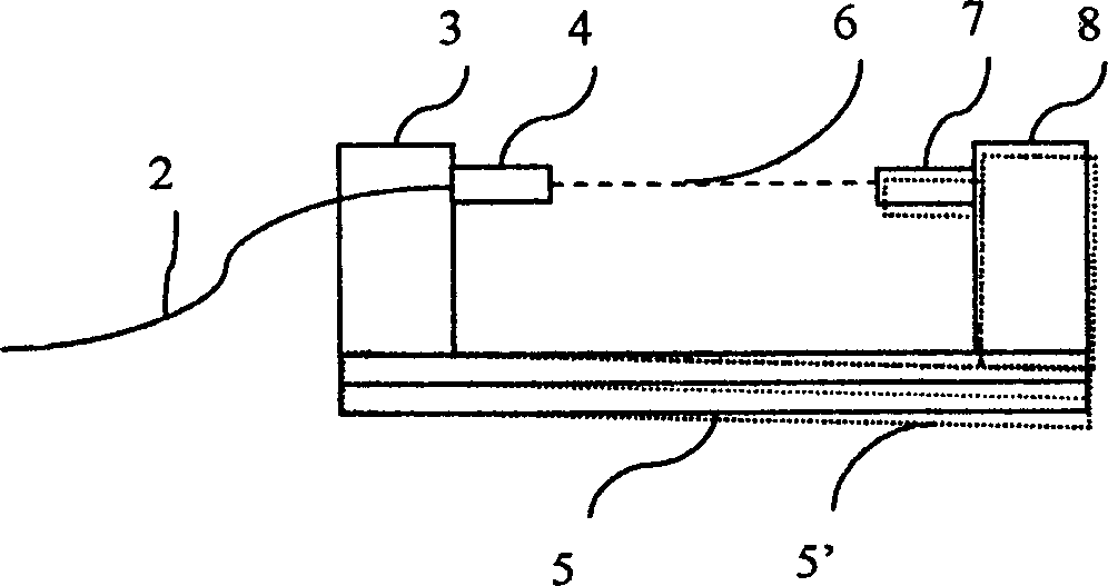
[0021] Example 1: If figure 1 As shown, the transmitter 4 and the receiver 7 constituting the optical path component are fixedly installed on the bimetal temperature-sensing component 5 through the connecting piece 3 and the connecting piece 8 respectively, and the incident light 1 is converted into the light beam 6 by the transmitter 4 through the optical fiber 2 and irradiated. to the receiver 7; the bimetallic temperature sensing member 5 is in contact with or as close as possible to the temperature measurement point, and the optical signal received by the receiver 7 is transmitted to the processing device 9 through the optical fiber 10. The processing device has functional devices such as photoelectric conversion, signal amplification, data processing, record display, and alarm. When the temperature of the temperature measuring point changes, the temperature of the bimetal temperature-sensing member 5 will change accordingly. Due to the stress generated by the thermal expa...

example 2

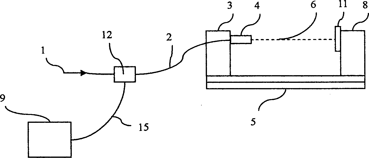
[0022] Example 2: If figure 2 As shown, the same temperature sensing member as in Example 1 was used, but the optical path member was reflective. The device 4 and the reflector 11, which are both transmitters and receivers, are fixedly installed on the bimetal temperature-sensing member 5 through the connecting piece 3 and the connecting piece 8 respectively, and the incident light 1 is converted into a light beam 6 by the transmitter 4 through the optical fiber 2 and irradiated. On to the mirror 11 , the light reflected by the mirror is received by the receiver 4 . Due to the temperature change of the temperature measuring point, the bending of the bimetal 5 causes the angle and distance between the reflector 11 installed on it and the transmitter 4 to change, so that the reflection of the reflector 11 onto the receiver 4 The optical power changes accordingly. The optical signal received by the receiver 4 is transmitted to the reflective optical splitter 12 through the opt...


PUM


Abstract

The photoelectric-mode temperature monitoring equipment combines the optical technology with the method of the traditional temperature measuring,its configuration simple and cost cheap.This equipmenthas a light path component fastened on a temperature-sensing component that is composed of two kinds of materials whose thermal-espansion coefficient are different,and the ilght path component can bethe combination of either the beam emitter which composes the perpendicular incidence light path and the beam receiver with the reflector,or the beam emitter which composes the reflecting light path and the beam receiver with the reflector.Abeam emitted from the emitter irradiates the beam receiver and is received by it,or the beam irradiates the reflector and is reflected intl the receiver,then hte beam is received by the receiver which is linked with the processing device by the receiver outputting light signals.

Description

technical field [0001] The invention belongs to the temperature monitoring technology and relates to a photoelectric sensing remote temperature monitoring device. Background technique [0002] Temperature sensing technology is one of the most widely used sensing technologies in industrial production and daily life. Using temperature sensing technology to measure and monitor temperature is of great significance in industrial production and daily life. At present, the widely used temperature monitoring technology mainly uses contact electric sensing technology, such as thermocouple type, thermal resistance type, integrated circuit type and other temperature sensing technologies. However, there are certain difficulties in the application of these technologies in some cases, such as in the fields of ultra-high voltage power transmission equipment, flammable and explosive materials, and conductive objects. In the temperature monitoring of ultra-high voltage transmission equipmen...

Claims


Application Information

Patent Timeline
Patent Type & Authority Applications(China)
IPC IPC(8): G01K5/70
Inventor 符建
Owner 符建
Why Eureka
Try Eureka