Electric machine driving device

A motor drive and voltage technology, applied in AC motor control, output power conversion device, electronic commutation motor control, etc., can solve the problems of motor 1 and mechanical system breakage, increase production cost, unstable speed control of motor 1, etc.

Inactive Publication Date: 2002-12-25
PANASONIC CORP
View PDF0 Cites 1 Cited by
  • Summary
  • Abstract
  • Description
  • Claims
  • Application Information

AI Technical Summary

Problems solved by technology

[0007] However, in case the load torque of the motor 1 is not constant with respect to the rotation angle of the motor 1, the residual torque caused by the difference between the output torque and the load torque makes the motor 1 The speed of the motor 1 changes constantly, so the speed control

Method used


Image

  • Electric machine driving device
  • Electric machine driving device
  • Electric machine driving device

Examples


Embodiment Construction

[0021] An embodiment of the present invention is described below with reference to the accompanying drawings. (Structure of motor drive unit)

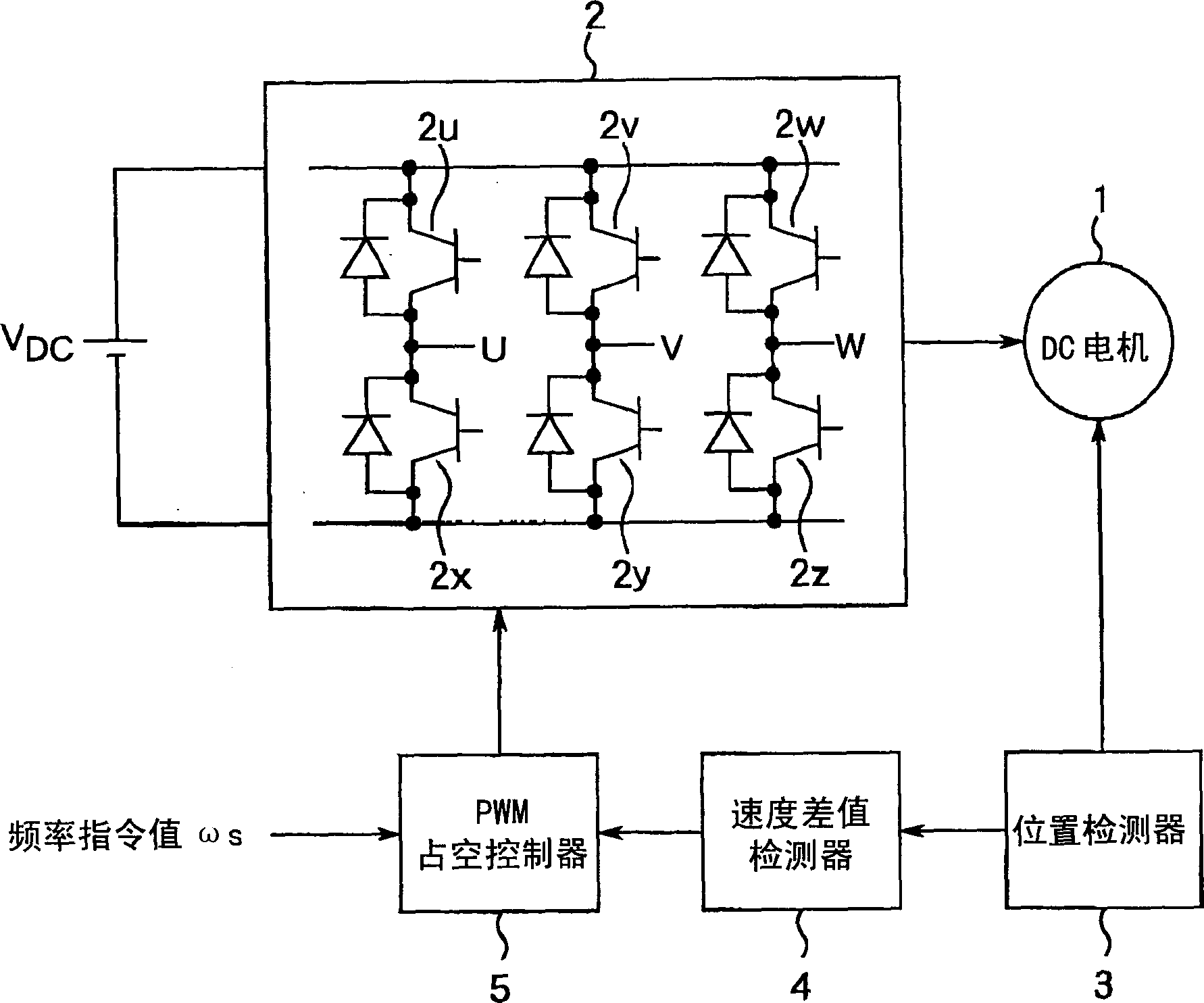
[0022] figure 1 The structure of the motor drive device according to the specific embodiment of the present invention is shown. figure 1 The motor drive device is arranged to be able to control the number of revolutions of the three-phase np poles (np is an even number not less than 4) of the brushless DC motor 1 by 120° excitation control (square wave excitation control).

[0023] Such as figure 1 As shown, this motor driving device includes: a DC / AC converter 2 for converting a DC voltage into a pseudo AC voltage to output a pseudo AC voltage to the motor 1; a magnetic pole position detector 3 for detecting the rotor position of the motor 1 ; A speed difference detector 4 for detecting the rotational speed of the motor 1 from the rotor position of the motor 1 measured by the magnetic pole position detector 3, and a pulse width ...


PUM


Abstract

PURPOSE: To provide a motor drive with a simple structure capable of reducing mechanical noises and vibrations. CONSTITUTION: In this motor drive which controls the rotational speed of a three-phase np (np: an even number more than or equal to 4) pole brushless DC motor, there are provided an DC-AC converting means for converting DC voltage into desired false AC voltage, a position detection means for detecting rotational phases obtained from the induced voltage of a three-phase armature winding of the brushless DC motor, and a duty control means for performing pulse width modulation(PWM) of the DC-AC converting means. The duty control means consists of a reference duty determining means for determining a reference duty value based on a frequency command value, a correcting means for correcting the reference duty value into an output duty value based on rotational speed for each angle range obtained by dividing a one-turn angle of the brushless DC motor into np portions, and an output means for outputting the output duty value.

Description

technical field [0001] The present invention relates to a motor drive for controlling the frequency of a brushless direct current (DC) motor. Background technique [0002] Such as Figure 7 As shown, a 120° excitation control (square wave excitation control) type motor drive device is known, which is used to control the number of revolutions of a three-phase np pole (np is an even number not less than 4) brushless DC motor. Such as Figure 7 As shown in , this known motor driving device includes a DC / AC converter 2 for converting a DC voltage into a pseudo AC voltage to output a pseudo AC voltage to the motor 1 and a magnetic pole position detection device for detecting the rotor position of the motor 1 Device 3. A pulse width modulation (PWM) duty controller 5' outputs an added voltage to the DC / AC converter 2 to control the number of revolutions of the motor 1, and outputs a duty signal to control the frequency and phase of the motor 1. The DC / AC converter 2 is composed ...

Claims


Application Information

Patent Timeline
IPC IPC(8): H02P6/10H02P6/06H02P6/08H02P6/18H02P6/182
CPCH02M7/5395H02P6/085H02P6/182H02P27/08
Inventor 东光英
Owner PANASONIC CORP
Why Eureka
Try Eureka