Fiber strand aggregating device for air slide

An air trough and fiber technology, which is used in textiles and papermaking, continuous winding spinning machines, drafting equipment, etc., can solve the problems of low yarn strength, increased yarn hairiness, and insufficient fiber alignment. Soft touch, improved wearing comfort, and increased gloss

Inactive Publication Date: 2003-01-01
DONGHUA UNIV
View PDF1 Cites 17 Cited by
  • Summary
  • Abstract
  • Description
  • Claims
  • Application Information

AI Technical Summary

Problems solved by technology

Most of the fibers at the edge and bottom protrude out of the yarn and become hairiness, which increases the hairiness of the yarn, and the arrangement of the fibers in the yarn is not straight, parallel, and compact enough, so that the yarn strength is also low

Method used


Image

  • Fiber strand aggregating device for air slide
  • Fiber strand aggregating device for air slide
  • Fiber strand aggregating device for air slide

Examples


Embodiment Construction

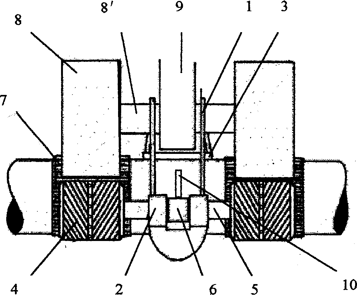
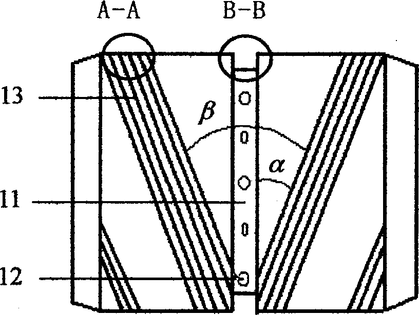
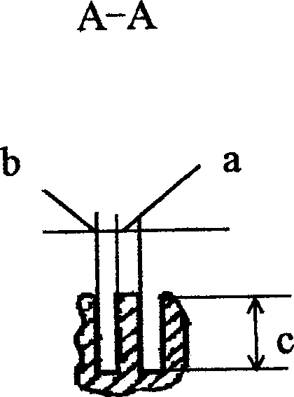
[0027] The invention provides a gathering device for polyfiber strands in an air trough, which is suitable for spinning frames. The polyfiber strand accumulating device in the air slot is installed between the outlet of the front nip in the drafting area of ​​the spinning frame and the spinning section, and the poly fiber strand accumulating device in the air slot and the front roller form a fiber nip, On the polyfiber whisker gathering device, several gathering airflows are added through the air holes 12 at the bottom of the gathering groove 11 to provide a flow field for the fibers in the split guiding groove 13 and the gathering groove 11. Through the splitting guide groove 13 of the airflow groove gathering fiber strand gathering device, the fiber strands are split and guided and the airflow in the gathering groove 11 is guided, and the fiber strands are gathered by the airflow in the gathering groove 11, so that the fibers The strands are tightly twisted in the gathering ...


PUM

PropertyMeasurementUnit
depthaaaaaaaaaa
widthaaaaaaaaaa

Abstract

The present invention is fiber strand aggregating device for air slide, and its novel design is its aggregating roller with new splitting guide flute and porous aggregating flute. It is installed between the front jaw and the spinning section in the drawing area of spinnin frame, and the air slide fiber strand aggregating device and the front roller form one fiber jaw. By means of the additional aggregating air flows, one flow field for fiber inside the guide flute and the aggregating flute is provided. By means of splitting and guide of the guide flute and the aggregating flute and the aggregation of fiber strand in the aggregating flute, the fiber strand is twisted closely in the aggregating flute. The yarn of the present invention has improved axial parallel degree, decreased hairy feather amount outside the yarn and raised yarn strength.

Description

Technical field: [0001] The invention belongs to the field of textiles, and relates to a new gathering device for polyfiber strands in an airflow slot, which is suitable for spinning frames. Background technique: [0002] In the traditional ring spinning production, after the roving entering the drafting zone is drafted in the rear zone and the front zone, each fiber in the roving is in a free state when it reaches the front nip. The difference between the yarn width of the spun yarn after twisting is large, and the yarn formation area at this time will form the so-called spinning triangle area. The fibers at the edge of the spinning triangle often cannot be twisted into the yarn and become fly and lost, or are rarely wrapped into the yarn. Most of the fibers at the edge and bottom protrude out of the yarn and become hairiness, which increases the hairiness of the yarn, and the arrangement of the fibers in the yarn is not straight, parallel, and compact enough to make the y...

Claims


Application Information

Patent Timeline
Patent Type & Authority Applications(China)
IPC IPC(8): D01H1/02D01H5/72
Inventor 程隆棣祝章琛于修业劳继红江慧薛文良
Owner DONGHUA UNIV
Why Eureka
Try Eureka