Method for centralizing illuminator of back light assembly and combined light guide plate

A technology of backlight assembly and light guide plate, which is applied in the direction of light guide, optical element, light guide of lighting system, etc., can solve the problems of wasting power and projecting on the A1 side of the light guide plate A, etc., to reduce the defect rate and improve the brightness of the light source. , the effect of reducing costs

Inactive Publication Date: 2003-01-29
刘保伸 +1
View PDF0 Cites 14 Cited by
  • Summary
  • Abstract
  • Description
  • Claims
  • Application Information

AI Technical Summary

Problems solved by technology

Please check the photo figure 1 , as shown in the figure: the general edge-lit backlight assembly, its main luminescent medium is composed of a light guide plate A, a cylindrical cold cathode tube B, and a reflector C: wherein the cold cathode tube B is set on the light guide A1 on the A side of the A board; therefore, it can be understood from the figure that the B1 light source on the side of the cylindrical cold cathode tube B is projected on the A1 side of the light guide plate A, and the B2 light source on the other side of the cylindrical cold cathode tube B is projected On the reflector C, the general side-lit backlight assembly uses the reflector C to reflect the light source from B2 on the other side of the cylindrical cold cathode tube B back to A1 on the side of the light guide plate A, but it will still be affected by the light source described by the light source. The barrier of the cylindrical cold cathode tube B itself cannot project all the light sources of the cylindrical cold cathode tube B on the side A1 of the light guide plate A; in addition, the light source of the cold cathode tube B will also be affected by the light guide plate The distance [L] of A decreases, so please refer to figure 2 As shown, a portable computer with a larger screen usually uses a longer cold-cathode tube C, which is placed on the longer side A11 of the light guide plate A, and then strives to shorten the length of the light guide plate A from the projection end of the light source of the cold-cathode tube C to the light guide plate. The end distance L1 is matched with the luminance of the projected light source of the reflector C and the reflection point D, so it also wastes precious power; please check the photo again figure 1 , due to the relatively large area and to ensure the luminance of the projected light source, the light guide plate A will be limited by the thickness on the side A1 because the longer L distance makes the light guide plate A wedge-shaped angle Therefore, it increases. In addition, manufacturing a flat and large-area light guide plate A is also a difficulty in production and subsequent processing, so the defective rate in manufacturing is also high.

Method used


Image

  • Method for centralizing illuminator of back light assembly and combined light guide plate
  • Method for centralizing illuminator of back light assembly and combined light guide plate
  • Method for centralizing illuminator of back light assembly and combined light guide plate

Examples


Embodiment Construction

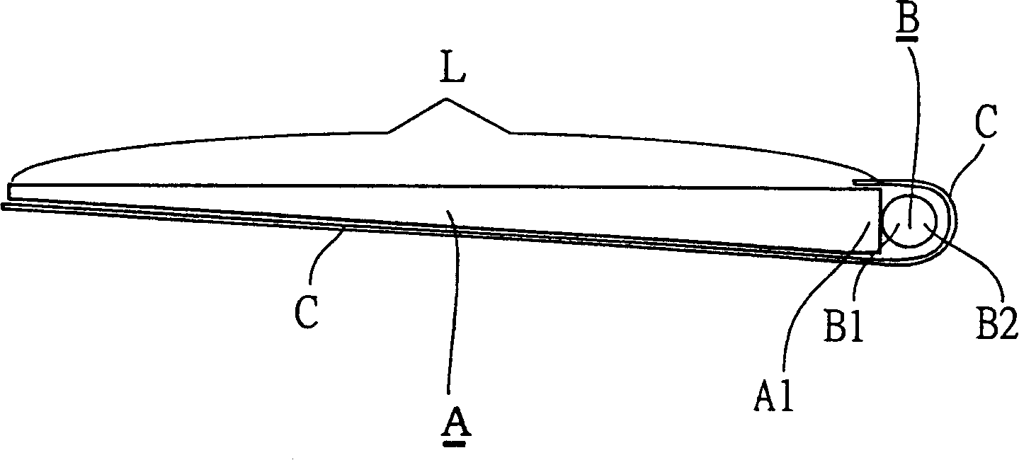
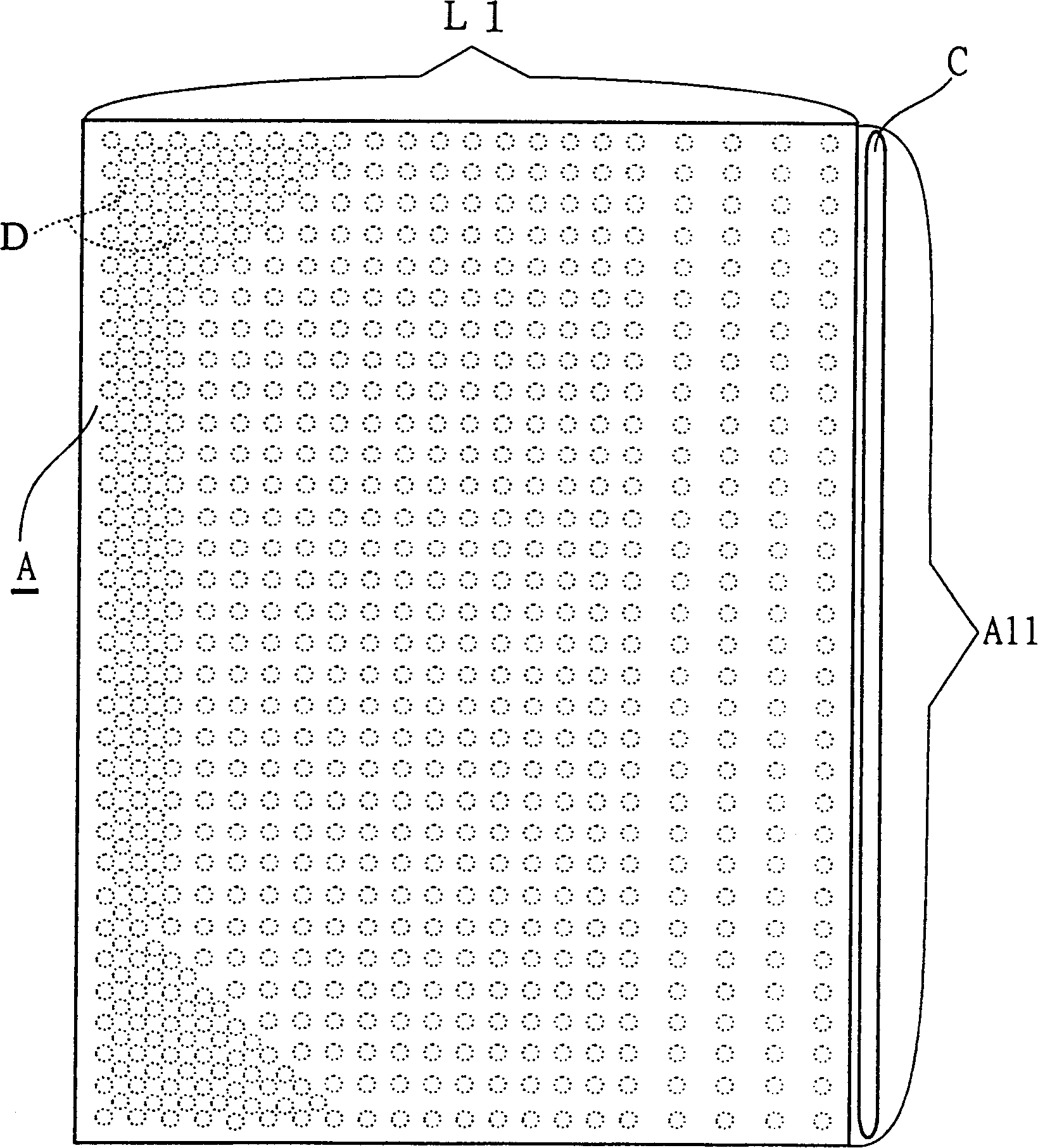
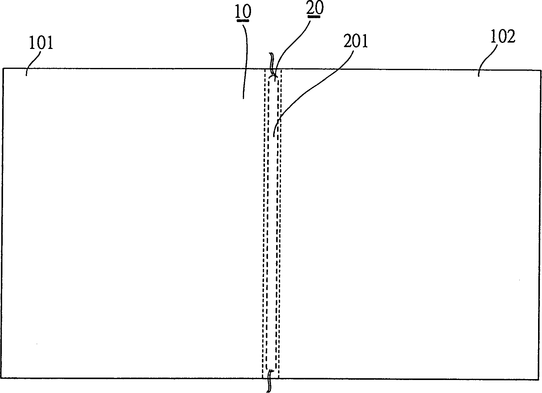
[0056] Please check the photo image 3 and Figure 4 ,like image 3 Shown, the present invention mainly is by; Have the light guide plate 10 and illuminant 20 that are sheet-like with two ends and constitute; Please check according to Figure 4 , which has two ends and is a sheet-shaped light guide plate 10, which extends to both sides into a pair of wedge shapes 101 and 102 in side view, and a groove 103 is provided at about the middle of the light guide plate 10; The light-emitting cold-cathode tube 201 is formed, and it is designed in the groove 103 at the middle section of the light guide plate 10, so that the light source of the light-emitting cold-cathode tube 20 will be thrown in from both sides of the groove 103, so it can be guided in the same size. Under the condition of the light plate, shorten the distance from the projection light source of the illuminant from one side of the light guide plate to the other side of the straight line, please refer to Figure 5, und...


PUM


Abstract

A combined light guide plate for back light assembly is composed of a light guide plate, a luminous body positioned in the center of light guide plate to divided it into two planes with specific angle and mutually foldable potential, and a light damping shield above the light guide plate and the luminous body for equalizing the brightness on the whole plate. The luminous body is composed of granular LEDs. It is suitable for large area.

Description

【Technical field】 [0001] The invention relates to a backlight assembly of a liquid crystal display electronic screen, in particular to a backlight assembly of a liquid crystal display electronic screen of a portable electronic product. 【Background technique】 [0002] In general, portable electronic products with liquid crystal display electronic screens, among which consumers will be very concerned about the size and thickness of the screen or whether it saves power, and the suppliers can also provide ultra-thin and larger screens and save energy. Electricity is the condition for peers to compete with each other and a bargaining chip to increase profits. However, the factors that affect the size and thickness of LCD electronic screens mainly come from the backlight components. Please check the photo figure 1 , as shown in the figure: the general edge-lit backlight assembly, its main luminescent medium is composed of a light guide plate A, a cylindrical cold cathode tube B,...

Claims


Application Information

Patent Timeline
IPC IPC(8): F21V8/00G02F1/1335G02F1/13357
Inventor 刘保伸
Owner 刘保伸
Why Eureka
Try Eureka