

Small scanning module with magnetic centring scanning mirror
A scanning module and scanning mirror technology, applied in the field of scanning modules, can solve the problem that barcode symbols are not the main function of the device
- Summary
- Abstract
- Description
- Claims
- Application Information
AI Technical Summary
Problems solved by technology
Method used
Image

Examples
Embodiment Construction
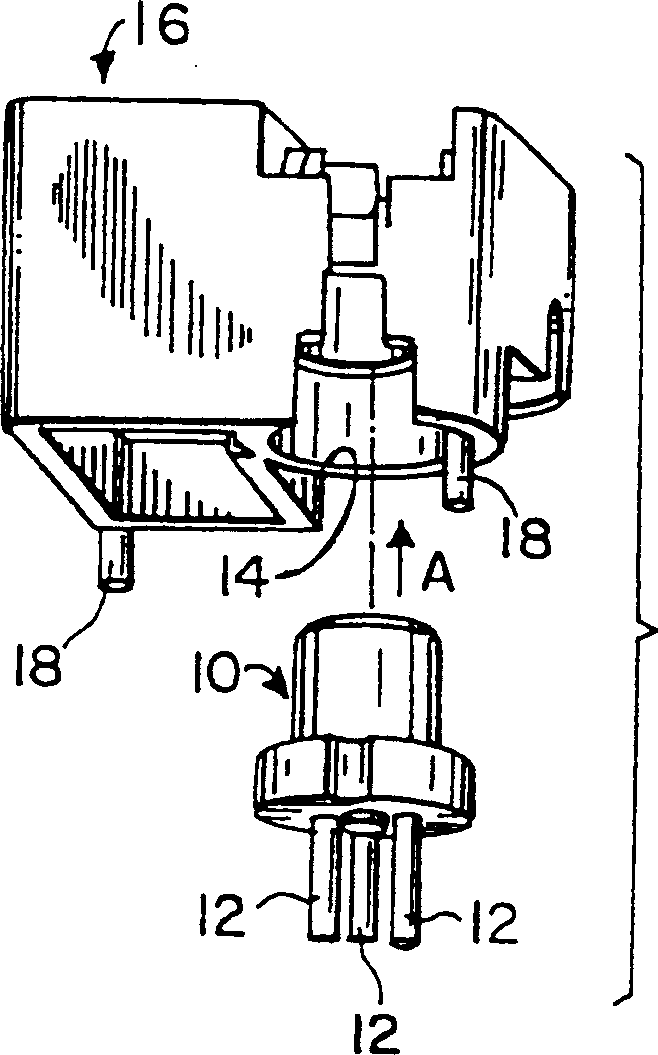
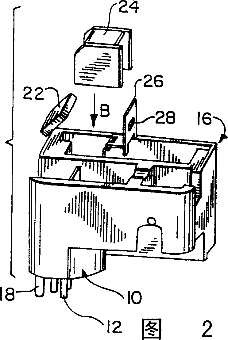
[0038] See attached picture below, figure 1The reference number 10 in represents a light source, which is preferably a semiconductor solid-state laser packaged in a shell, the shell has a plurality of pins 12 protruding from the bottom wall of the shell, and the laser is suitable for passing through the shell when it is energized. A through hole in the upper wall emits a laser beam, preferably a visible laser beam. The housing 12 is inserted in the direction of arrow A into a cylindrical hole 14 in a support or frame 16 having a plurality of mounting posts 18 inserted into and extending through Image 6 Corresponding mounting holes are shown for a substantially planar base plate 20 , which is preferably an underlying printed circuit board (PCB) supported by frame 16 . Frame 16 supports laser 10 and all other elements of a scanning module or assembly, as described below.
[0039] As shown in Figure 7, the bottom wall of the shell rests on the upper surface of the printed circ...
PUM
 Abstract
Description
Claims
Application Information