Imaging signal processing method and device

An image signal processing and image signal technology, applied in image communication, video signal space resolution conversion, television, etc., can solve the problem of multi-storage capacity, achieve the effect of simplifying the structure, reducing the scale of the circuit, and eliminating poor image quality

Inactive Publication Date: 2003-02-05
PANASONIC CORP
View PDF0 Cites 1 Cited by
  • Summary
  • Abstract
  • Description
  • Claims
  • Application Information

AI Technical Summary

Problems solved by technology

Therefore, there is a tendency for the circuit scale to expand as the format of the image signal that can be input increases.
In addition, in order to correspond to the image signal format with a large screen size, a large amount of storage capacity is required

Method used


Image

  • Imaging signal processing method and device
  • Imaging signal processing method and device
  • Imaging signal processing method and device

Examples


Embodiment 1

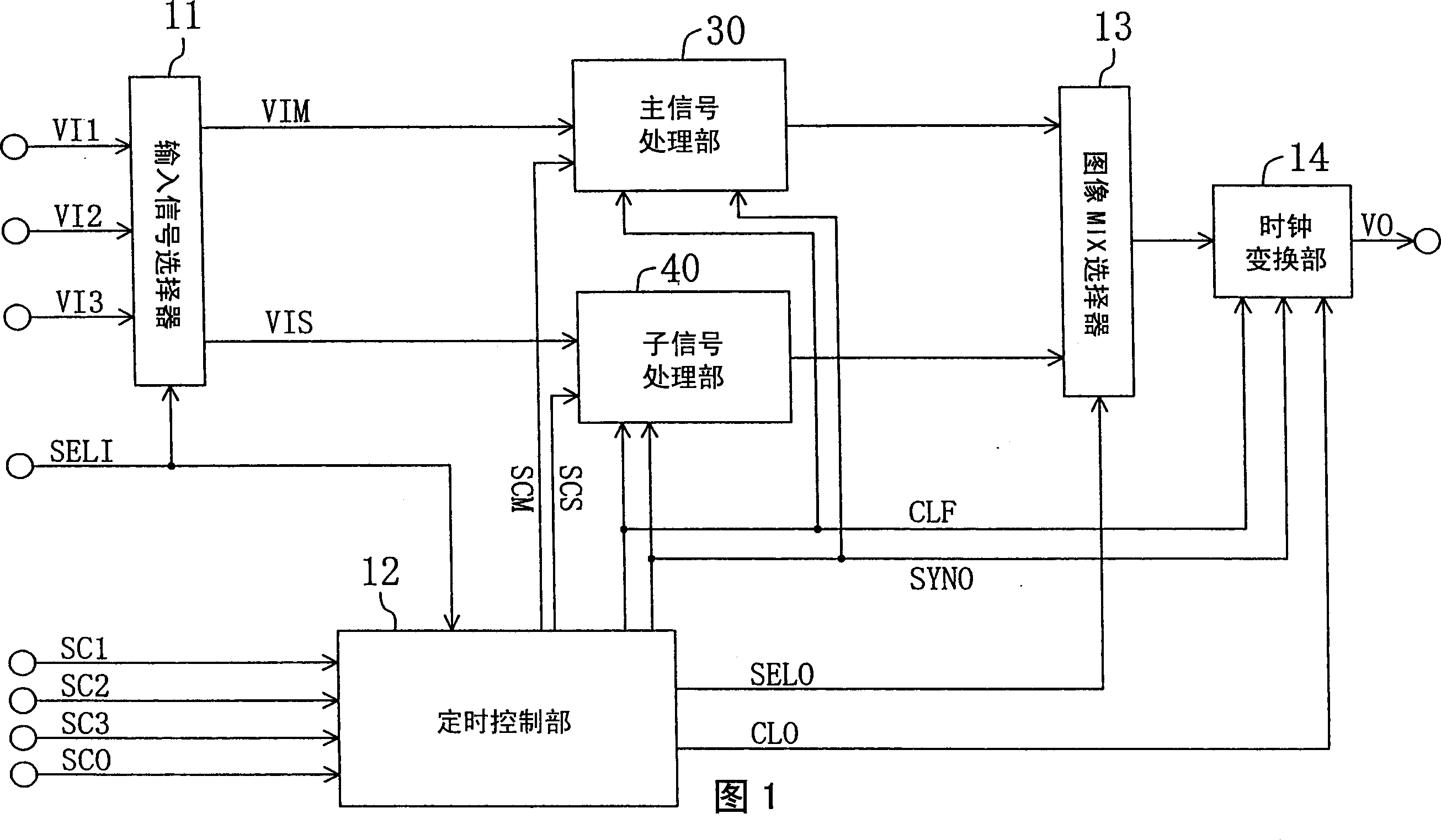
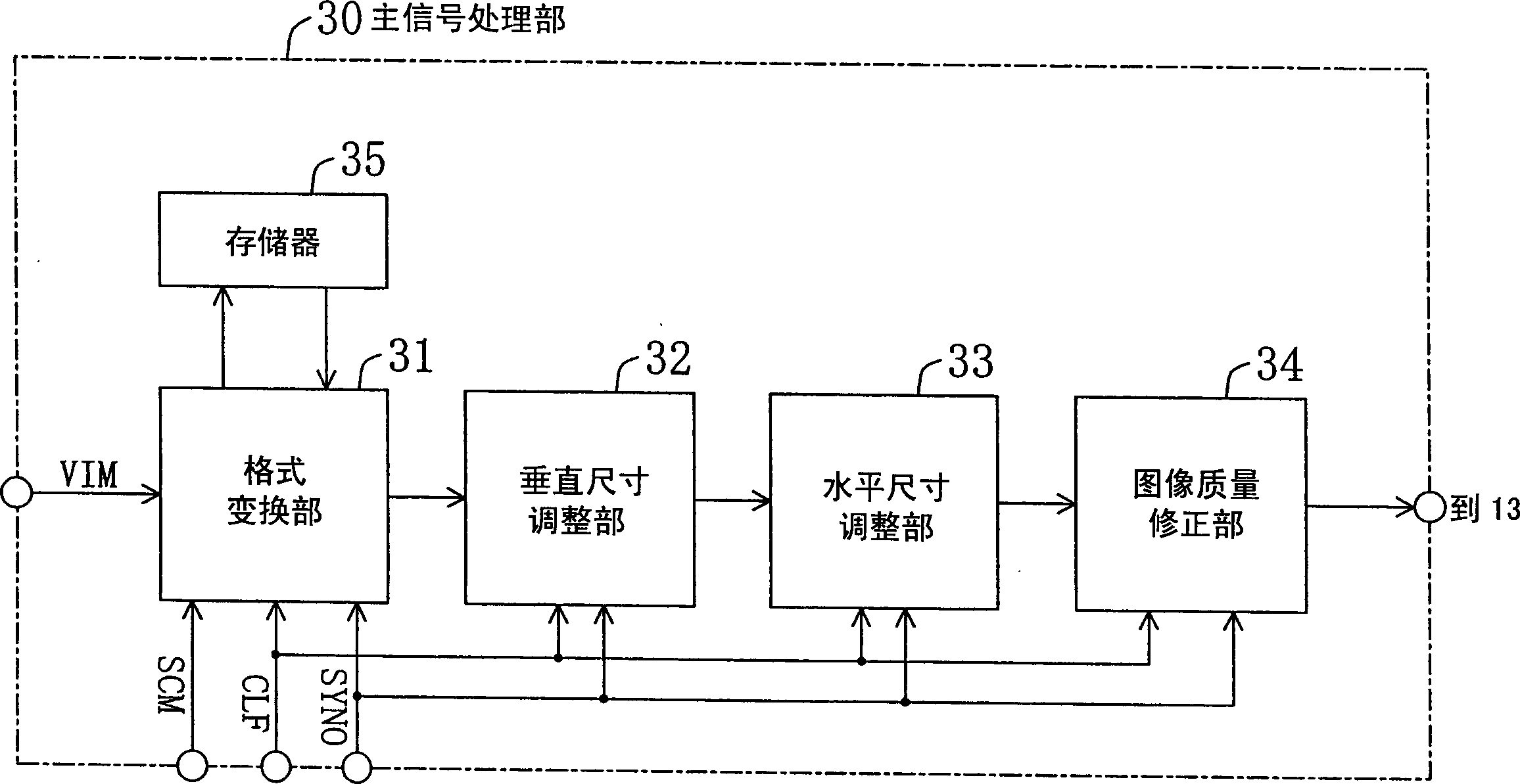
[0080] FIG. 1 is a block diagram of an image signal processing apparatus according to Embodiment 1 of the present invention. The image signal processing device of FIG. 1 includes: an input signal selector 11 as an input signal selection section, a timing control section 12, a main signal processing section 30, a sub-signal processing section 40, an image MIX selector 13 as an image synthesis section, a clock Transformation section 14.

[0081] Input image signals VI1 , VI2 , and VI3 of three systems and an input selection signal SELI are input to an input signal selector 11 . These image signals are digital signals such as those of televisions and personal computers. The input signal selector 11 selects one of the input image signals VI1, VI2, and VI3 as the main image signal VIM and the other one as the sub image signal VIS according to the input selection signal SELI, and outputs the main image signal VIM to the main signal processing unit 30. , output the sub-image signal...

Embodiment 2

[0100] Figure 7 is a block diagram of an image signal processing device according to Embodiment 2 of the present invention. Figure 7 In the image signal processing device of FIG. 1 , the main signal processing unit 130 is used to replace the main signal processing unit 30, the sub signal processing unit 140 is used to replace the sub signal processing unit 40, and the main image correction unit is also provided. 134 and sub-image correction unit 144. Furthermore, the unit has a clock conversion unit 14 . The output clock CLO is also input to the main signal processing unit 130 and the sub signal processing unit 140 . The high-speed clock CLF is not input to the sub-signal processing unit 140 .

[0101] Figure 8 yes Figure 7 A block diagram of the main signal processing unit 130. The master signal processing section 130 is a slave figure 2 obtained by removing the image quality correction unit 34 from the main signal processing unit 30 of . The output clock CLO is i...

Embodiment 3

[0118] Fig. 11 is a block diagram of an image signal processing device according to Embodiment 3 of the present invention. The image signal processing device of Fig. 11 is in Figure 7 The image signal processing device further includes a main input selector 21 as a main image selection unit. In order to avoid cumbersomeness, in the figures described below, the display of the timing control unit 12, the synchronization signal, and the clock is omitted.

[0119] The main image signal VIM and the output signal of the sub-signal processing unit 140 are input to the main input selector 21 . The main input selector 21 selects these signals according to the main selection signal SELM output from the timing control unit 12 , and outputs them to the main signal processing unit 130 .

[0120] In the third embodiment, the case where an input image signal of one system is taken as an object, and the image signal is processed by the main signal processing section 130 after the sub-signa...


PUM


Abstract

A video signal processing method is employed in a video signal processing apparatus that includes a plurality of signal processing parts, each for executing signal processing, for processing two or more digitalized video signals in parallel, and the video signal processing method includes the steps of selecting one or more video signals from the two or more digitalized video signals; and obtaining an object video signal by selecting, from the plurality of signal processing parts, signal processing parts used for signal processing of the selected video signals in accordance with a mode of the object video signal and executing the signal processing in the selected signal processing parts in an order in accordance with the mode of the object video signal. To enable adaptation to more formats and output styles of input video signal without making a circuit scale large.

Description

technical field [0001] The present invention relates to an image signal processing method and apparatus, and more particularly to an image signal processing method and apparatus for performing processing for displaying an image signal on a display unit. Background technique [0002] In recent years, digital signal processing of image signals has begun. In addition, the signals input to the imaging equipment are divided into TV signals, personal computer signals, game machine signals, etc., and are diversified, and there are various formats for each of these signals. Therefore, display components such as CRT (cathode-ray tube, cathode ray tube), liquid crystal, and PDP (plasma display panel, plasma display panel) for displaying image signals are required to be able to correspond to more image signal formats. [0003] In addition, as for the display part, not only is it required to display one of image signals in various formats, but it is also required to have a function of ...

Claims


Application Information

Patent Timeline
Patent Type & Authority Applications(China)
IPC IPC(8): G09G5/00G09G5/18H04N3/27H04N5/45H04N5/46
CPCH04N7/0122H04N21/4316H04N21/4307H04N5/45H04N5/44591H04N21/44004H04N21/4347H04N21/440263H04N21/440218H04N21/47H04N21/43072
Inventor 三木阳一郎寒川贤太
Owner PANASONIC CORP
Why Eureka
Try Eureka