Organic electroluminescent element

An electroluminescence component, organic technology, applied in the direction of electrical components, electroluminescence light source, electric light source, etc., can solve the problem of thin and short device design, difficult to withstand the impact of external force, display crosstalk and other problems, to achieve the suppression of black spots Generate and strengthen the effect of light, thin and short, and strengthen the impact resistance

Inactive Publication Date: 2003-02-05
OPTO TECH
View PDF5 Cites 13 Cited by
  • Summary
  • Abstract
  • Description
  • Claims
  • Application Information

AI Technical Summary

Problems solved by technology

[0008] 1. It is impossible to meet the high-definition requirements for the pattern of organic EL elements. For the edges of the two electrodes, it is easy to cause a small short circuit and cause the problem of display crosstalk (Crosstalk);
[0009] 2. The isolation sealing layer directly covers the surface of the substrate without any supporting pillars, which makes it difficult to withstand the impact of external forces, which has certain problems for the design of light, thin and small devices; and
[0010] 3. This kind of organic EL element structure is difficult to be used as the basic structure of full-color light emission, and there are certain restrictions on the scope of use of the element

Method used


Image

  • Organic electroluminescent element
  • Organic electroluminescent element
  • Organic electroluminescent element

Examples


Embodiment Construction

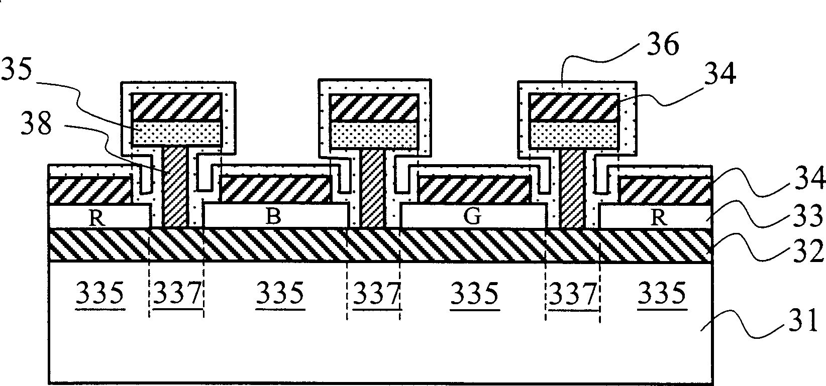
[0057] First, see image 3 , is a cross-sectional view of the structure of a preferred embodiment of the present invention: as shown in the figure, firstly, a lower electrode 32 made of a transparent material (such as ITO) is formed on a substrate 31, and then a spin coat (spin coat) is used to , dipping (dipping), vapor deposition, sputtering, etching and other film forming and patterning methods form the isolation ribs 38 in a crossed state on the surface of the lower electrode 32, and are located at the vertical extension position of the isolation ribs 38 and the dry flange 35 with a cross-sectional area greater than that of the isolation rib 38, the bottom of the isolation rib 38 is a non-luminous area 337, and between the two non-luminous areas 337 is a preset luminous area 335, and then by the general conventional On the surface of the lower electrode 32 of the predetermined light-emitting region 335, an organic layer 33 including at least one organic emitting layer (org...


PUM


Abstract

The invention relates to the organic light component excited by electricity, especially the organic light component with the tube added in order to absorb more moisture to restrain the production of the black dot. Thus the quality of the light component is insured. The main structure of the light component includes the base plate, the lower electrode, the multiple insulation bearing ribs, at least one organic layer and the opposite electrodes. The insulation bearing ribs are made from phosphosilicate glass (PSG), which possesses the properties of absorbing moisture and insulating, located on the surface of the lower electrode. Since the ribs absorb the moisture or oxygen around the organic light components effectively, the probability of producing the black sports is reduced.

Description

technical field [0001] The invention relates to a light-emitting element, in particular to an organic electroluminescent element. Background technique [0002] Organic electroluminescent device (Organic electroluminescent device, hereafter referred to as organic EL device) has a large viewing angle, low response time, thin display, low power consumption, simple manufacturing process, impact resistance, no backlight and full-color emission Due to the advantages of the light source, it has attracted attention and been used in the new generation of display panels. [0003] see figure 1 , is a cross-sectional view of the structure of a conventional organic electroluminescent element, which mainly forms a lower electrode (transparent electrode) 12 on a substrate 11, and forms a hole in sequence at an appropriate position of the lower electrode 12, which may include a hole Injection layer (hole injection layer), hole transport layer (hole transport layer), organic emission layer...

Claims


Application Information

Patent Timeline
Patent Type & Authority Applications(China)
IPC IPC(8): H05B33/04H05B33/12
Inventor 庄丰如
Owner OPTO TECH
Why Eureka
Try Eureka