Cloth pressuring device of sewing machine

A cloth pressing device and sewing machine technology, which is applied in the direction of sewing machine components, cloth pressing mechanism, sewing equipment, etc., can solve the problems of inability to convey cloth, reduce operating efficiency, and uneven left and right deviation of cloth, so as to prevent needle pitch confusion and prevent damaged effect

Inactive Publication Date: 2003-02-19
YAMATO SEWING MASCH MFG CO LTD
View PDF0 Cites 8 Cited by
  • Summary
  • Abstract
  • Description
  • Claims
  • Application Information

AI Technical Summary

Problems solved by technology

[0004] However, for example, when the sewing object is a cloth with an uneven surface such as a wet suit cloth covered with waterproof rubber or coated, the sliding between the pressing surface of the cloth presser foot and the surface of the cloth is poor and both The contact area is also large, so the friction resistance is very large. As a result, the two are in a braking state, and the cloth cannot be conveyed smoothly. It is easy to produce the unfavorable phenomena of disordered needle pitch and poor sewing process
[0005] In order to prevent this kind of bad phenomenon in the sewing process, conventionally, when the cloth with a rough surface is used as the sewing object, the method of applying oil such as lubricating oil on the surface of the cloth in advance to make the sliding smooth is used before sewing. However, in this case, the sewing operation of applying oil to the surface of the cloth in advance and degreasing after sewing increases too many procedures that are not directly related, which not only leads to a decrease in work efficiency, but also The problem of oil contamination of sewn products inevitably arises

Method used


Image

  • Cloth pressuring device of sewing machine
  • Cloth pressuring device of sewing machine
  • Cloth pressuring device of sewing machine

Examples


Embodiment Construction

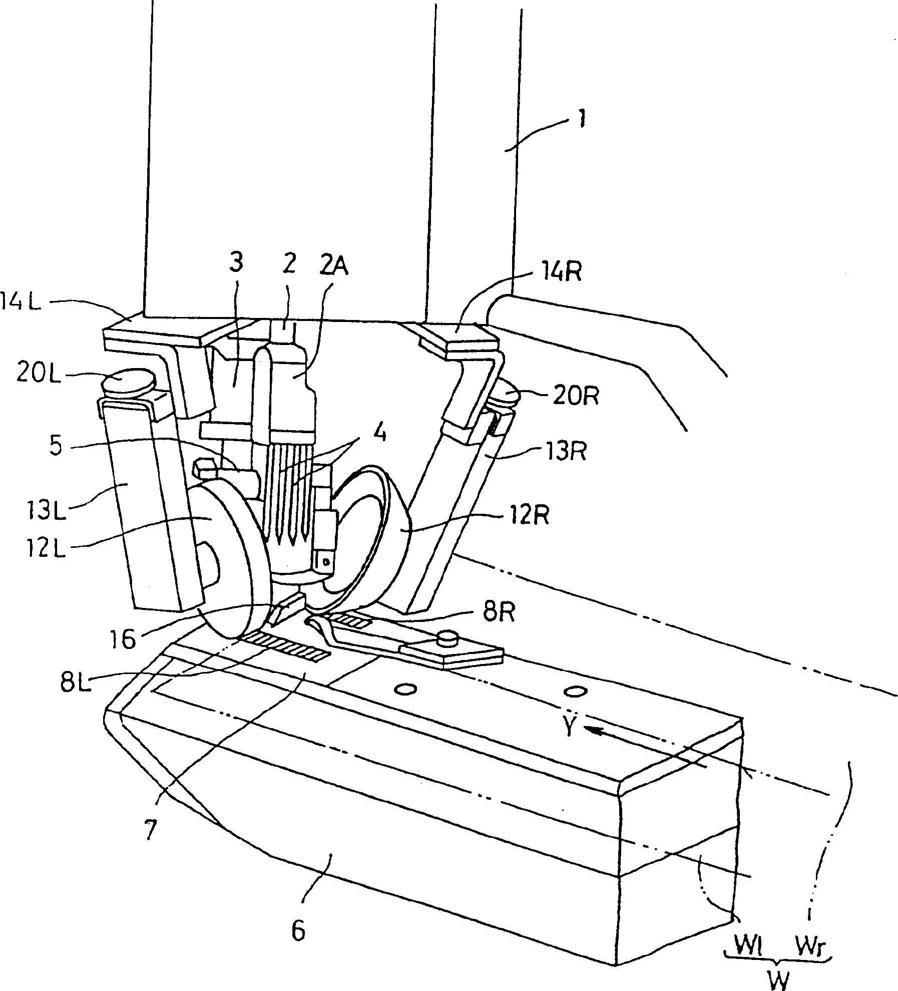
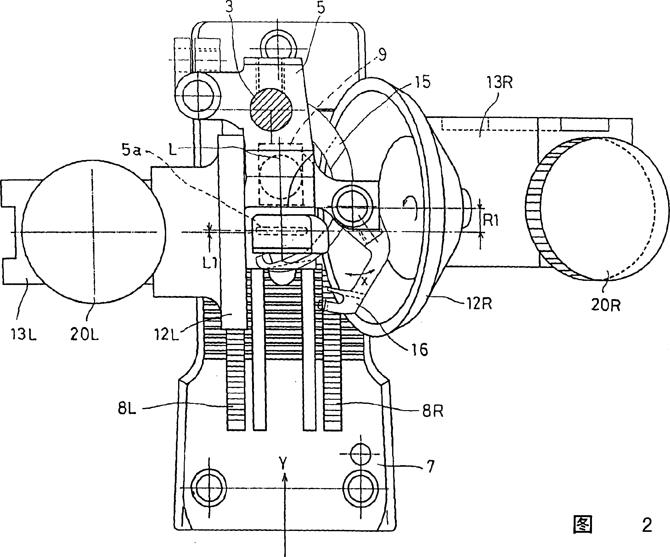
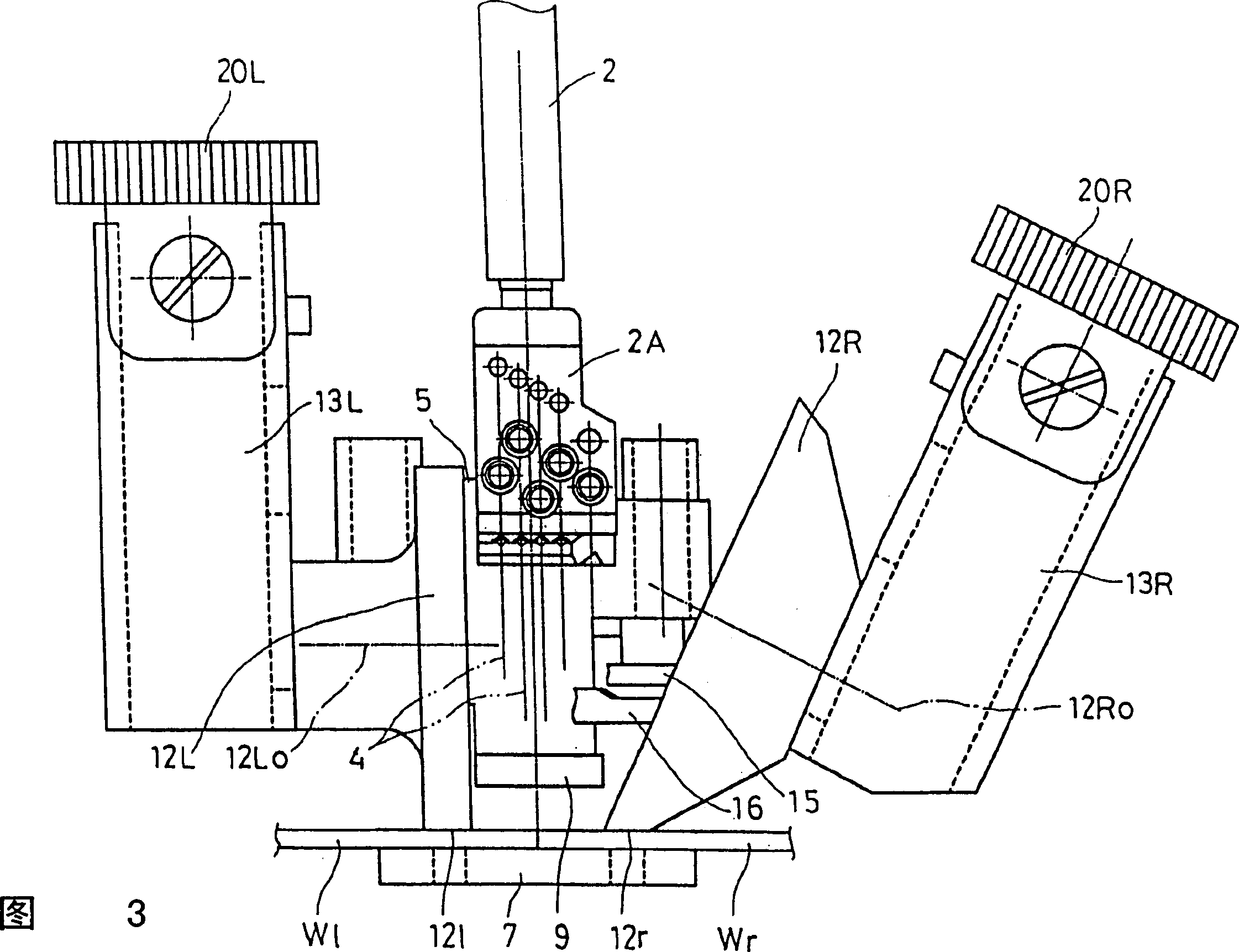
[0030] figure 1 It is a perspective view of the vicinity of the needle drop part of the cantilever sewing machine output by the cloth pressing device in the first embodiment of the present invention. At the tip of the sewing machine arm frame 1, it is juxtaposed front and back along the sewing forward direction Y and can freely reciprocate up and down. The needle bar 2 and the pressing bar 3 are supported droopingly. At the same time, several needles 4 are installed at the lower end of the needle bar 2 through the needle clamp 2A, and the lower end of the pressing bar 3 is fixedly supporting the presser foot body 5 .

[0031] On the other hand, a needle lifter 7 is fixed on the narrow tube type cylinder head 6. At the same time, in the cylinder head 6 at the lower part of the needle lifter 7, in addition to a pair of movable conveying teeth 8L, 8R, there is also a Place the parts for forming loops or sutures of the conveying mechanism (because these are well known, their detai...


PUM


Abstract

In this invention, a small presser foot elastically pressing a fabric on the downstream side of a sewing direction of a needle location hole against moveable feed dogs on the top face side of a needle plate is mounted, a pair of right and left rotors and elastically pressing the fabric against the moveable feed dogs by the peripheral lower ends and are provided, and the straight line distance along the sewing direction between the peripheral lower ends and of the pair of right and left rotors and the pressing portion of the small presser foot is reduced as much as possible to the extent that there is no interference with operation. Accordingly, this invention is able to reliably, smoothly and uniformly feed fabric without necessitating the trouble of applying oil when sewing the less smooth fabric and easily carrying out a curve stitch and a fancy stitch.

Description

field of invention [0001] The invention relates to a cloth pressing device of a sewing machine. Specifically, it relates to the case where the ends of the cloth are covered or coated with a waterproof rubber film, the cloth for wet suits, etc. are thick and the surface is very rough, with the ends facing each other or the ends overlapping The sewing machine pressing device used below. Background technique [0002] In the past, this kind of sewing machine pressing device, in order to smoothly convey the cloth placed on the needle jack plate in a straight line without shifting left and right along the sewing advance direction, the general structure is that it can freely reciprocate up and down. A cloth presser such as a leaf spring is installed at the lower end of the pressing rod, and the cloth presser such as a leaf spring elastically presses the cloth part on the top of the needle jack at positions corresponding to the front and rear conveying teeth arranged at the lower p...

Claims


Application Information

Patent Timeline
Patent Type & Authority Applications(China)
IPC IPC(8): D05B29/10D05B27/10D05B29/00
Inventor 林田高幸势力透
Owner YAMATO SEWING MASCH MFG CO LTD
Why Eureka
Try Eureka