Laser induced fluorescence detector

A laser-induced fluorescence and detector technology, applied in fluorescence/phosphorescence, instruments, measuring devices, etc., can solve the problems of easy damage to the eyes, inconvenience of photomultiplier tubes, and difficulty in the accurate location of laser points, etc., to achieve background signal reduction, easy Operation, the effect of suppressing stray light

Inactive Publication Date: 2003-03-05
DALIAN INST OF CHEM PHYSICS CHINESE ACAD OF SCI
View PDF0 Cites 19 Cited by
  • Summary
  • Abstract
  • Description
  • Claims
  • Application Information

AI Technical Summary

Problems solved by technology

The problem with this device is that the photomultiplier tube needs to be removed during observation, which is very inconvenient for the expensive and fragile photomultiplier tube; the laser beam directly irradiating the sample cell will generate a large amount of scattered light, which is difficult to directly observe The exact position of the laser point, and it is easy to damage the eyes

Method used


Image

  • Laser induced fluorescence detector
  • Laser induced fluorescence detector
  • Laser induced fluorescence detector

Examples


Embodiment Construction

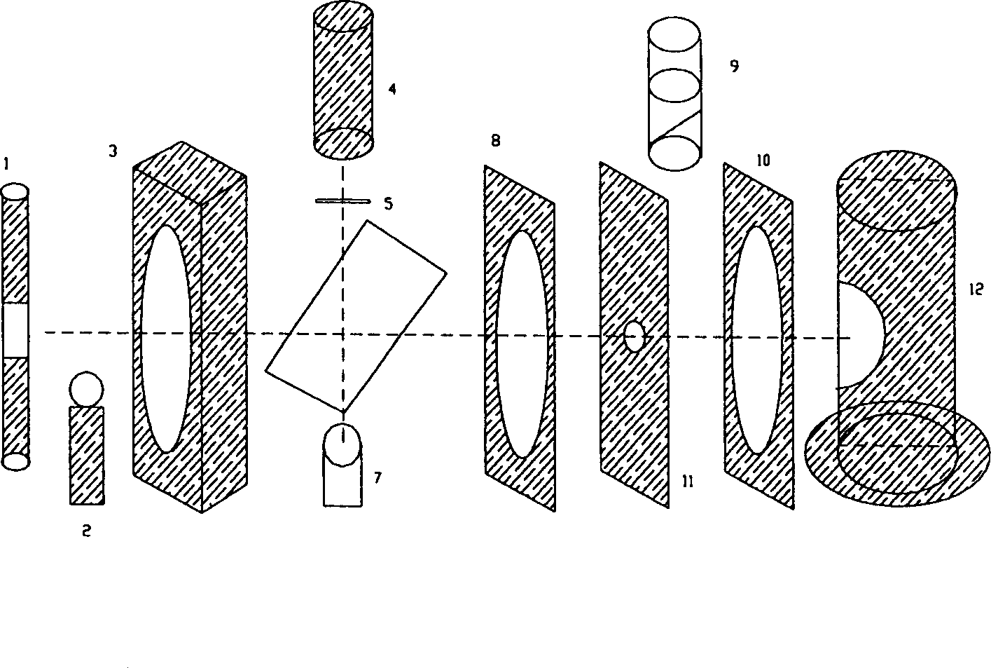
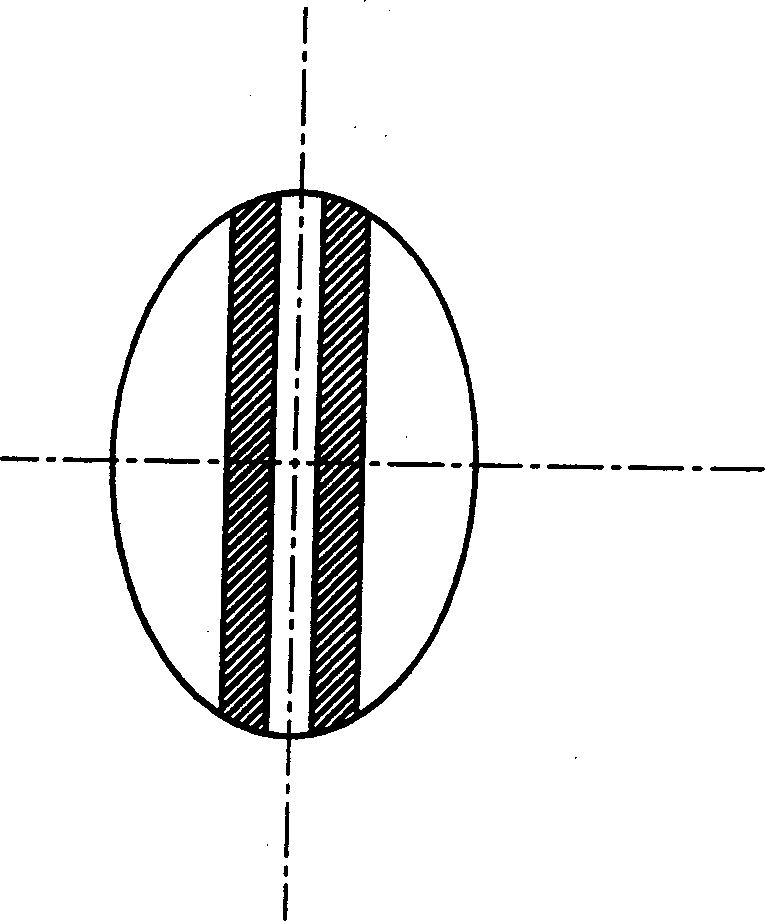
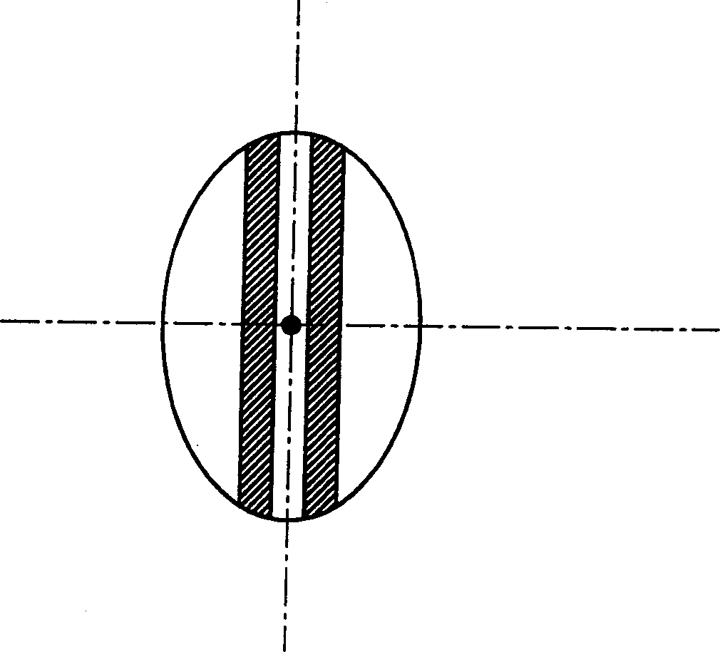
[0023] See first figure 1 , Figure 2a, b and Figure 3a, b. When calibrating the optical path, turn on the auxiliary light source 2 arranged between the sample cell 1 and the focusing lens 3, and rotate the observation mirror 9 to the observation point between the diaphragm 11 and the filter 10 (just located in the optical path), the sample cell 1 placed on the fine-tuning device 20. The structure of the fine-tuning device 20 is shown in Figures 3a to 3b. The middle part of the fine-tuning device 20 is provided with a position 22 where the sample pool 1 is placed and is in the shape of a round hole, and a horizontal moving rod 21 is provided. By adjusting the horizontal moving rod 21, the The horizontal slider 23 and the vertical slider 24 slide on the slideway base 25 to make the sample pool 1 move up, down, left, and right within a certain range.

[0024] Adjust the fine-tuning device 20 and the lens 3 so that the sample cell 1 presents a clear image at the aperture 11. Fig...


PUM

PropertyMeasurementUnit
wavelengthaaaaaaaaaa

Abstract

The invention is a laser-inducing-fluorescence detector. It includes: a piece of inching equipment to plant and ajdust the position of sample holder; an aided light source to adjust the light path; an observation mirror for adjusting the light path; an exciting light source as its working light source made up of the laser, the reference photoelectric diode and light-reducing board and the dichroiscope; a group of optical lenses in imagine and focus the working light source, made up of the focus lens, the imagining lens, the light-filtering piece and the light diaphragm; and a photoelectric signal converter to receive and output the detecting signal. The invention is based on the common-focus mode to get the high-efficiency imagining system and it can be used in the separating-analysis technique such as Micro-HPLC, CE, CEC and so on.

Description

technical field [0001] The invention relates to a laser-induced fluorescence detector. Background technique [0002] The micro-column separation and analysis system has incomparable advantages over traditional separation and analysis systems: high column efficiency, can greatly reduce the consumption of solvents and samples, has little environmental pollution, and is easy to use online with other detection methods. The advantages of the micro-column analysis system make it widely used in the technical fields of environmental science, natural products, petrochemical industry and biology. [0003] In micro-column analysis, due to the small injection volume (nanoliters) and low sample concentration, very high requirements are placed on the detector. Laser-induced fluorescence detection has very high sensitivity (ppb-ppt level), and the laser beam can be converged into a very small spot, which is well matched with the microcolumn system. It is these advantages that make laser-i...

Claims


Application Information

Patent Timeline
Patent Type & Authority Applications(China)
IPC IPC(8): G01N21/64G01N30/74
Inventor 黄威东车讯关亚风杨丙成
Owner DALIAN INST OF CHEM PHYSICS CHINESE ACAD OF SCI
Why Eureka
Try Eureka