Gray tone mask defect detecting method and device, and optical mask defect detecting method and device

A technology for defect inspection and gray-tone masking, which is applied in the direction of measuring devices, optical testing of defects/defects, optics, etc., and can solve problems such as non-detection and high detection sensitivity

Inactive Publication Date: 2003-03-12
HOYA CORP
View PDF0 Cites 6 Cited by
  • Summary
  • Abstract
  • Description
  • Claims
  • Application Information

AI Technical Summary

Problems solved by technology

If the threshold value is set low, the detection sensitivity becomes high, but it must be set to a level that does not detect suspected defects

Method used


Image

  • Gray tone mask defect detecting method and device, and optical mask defect detecting method and device
  • Gray tone mask defect detecting method and device, and optical mask defect detecting method and device
  • Gray tone mask defect detecting method and device, and optical mask defect detecting method and device

Examples


Embodiment Construction

[0060] Hereinafter, the defect inspection method and defect detection apparatus of the gray-tone mask with the gray-tone portion will be specifically explained.

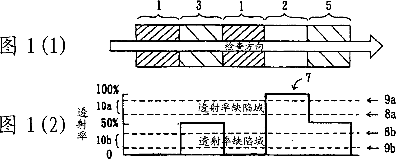
[0061] Fig. 1 (1) shows a case where no defect occurs in the light shielding portion 1, the transmissive portion 2, and the gray tone portions 3, 5. The arrow indicates the scanning direction (inspection direction) of the lens of the inspection device.

[0062] Fig. 1(2) shows the transmittance signal 7 obtained along the aforementioned scanning direction. The transmittance signal has a transmittance of 0% in the light shielding portion 1, a transmittance of 100% in the transmissive portion 2, and a transmittance of 50% in the gray tone portions 3 and 5.

[0063] The present invention is characterized in that a certain threshold is set for the above-mentioned transmittance signal to detect transmittance defects.

[0064] Specifically, as shown in Figure 1 (2), a threshold value for transmittance defects (8a on the upper ...


PUM


Abstract

The present invention provides a defect inspecting method and device capable of securing the transmittance in a gray tone part in a gray tone mask. The solution of the present invention is to provide a defect inspecting method for the gray tone mask having a gray tone part, which is to adjust the transmittance through the area of light shielding part, a light transmitting part, whose purpose is to reduce the amount of light transmitted through the area for selectively changing the film thickness of the photoresist; using a transmittance signal obtained by scanning a pattern inside the mask, threshold values 8a and 8b of a transmittance defect in the gray tone part are set on the transmittance signal 7, and when the transmittance exceeds the threshold values 8a and 8b, the occurrence of a transmittance defect is determined in the gray tone part.

Description

Invention field [0001] The present invention relates to a defect inspection method and a defect inspection device of a grey tone mask and a photomask containing fine patterns. Background technique [0002] In recent years, in the field of masks for large LCDs, attempts have been made to reduce the number of masks by using gray-tone masks (monthly FPT Intelligence, May 1999). [0003] Here, the gray tone mask, as shown in FIG. 6(1), has a light shielding portion 1, a transmissive portion 2, and a gray tone portion 3 on a transparent substrate. The gray tone portion 3 is, for example, an area where the light shielding pattern 3a within the resolution limit of a large LCD exposure machine using a gray tone mask is formed, and its purpose is to reduce the amount of light transmitted through the area and reduce the irradiation of the area The film thickness of the photoresist can be changed optionally. 3b is the fine transmissive part within the resolution limit of the exposure machin...

Claims


Application Information

Patent Timeline
Patent Type & Authority Applications(China)
IPC IPC(8): G01N21/956G03F1/84
CPCG03F1/84G01N21/956G03F1/50
Inventor 中西胜彦
Owner HOYA CORP
Why Eureka
Try Eureka