Cold air driven spray painter

A technology of cold air power spraying and spraying room, which is applied in spraying device, liquid spraying device, and device for coating liquid on the surface, etc., can solve the problems of limiting the use range of thermal spraying, limiting the size of spraying workpieces, and expensive spraying equipment, etc. Achieve the effect of improving powder feeding method, good spraying quality and long service life

Inactive Publication Date: 2003-03-19
INST OF METAL RESEARCH - CHINESE ACAD OF SCI
View PDF3 Cites 72 Cited by
  • Summary
  • Abstract
  • Description
  • Claims
  • Application Information

AI Technical Summary

Problems solved by technology

Because thermal spraying requires a very high temperature during the spraying process, when the flame stream leaves the nozzle, it will be exposed to a large amount of air, which will seriously oxidize the sprayed material, thus limiting the scope of thermal spraying.
In order to solve the above oxidation problem, the further improvement of thermal spraying technology is to use low-pressure plasma spraying and vacuum plasma spraying, but the size of the sprayed workpiece is limited in the vacuum chamber, and the coating can only be prepared for powder materials with a stable liquid phase, and Spraying equipment is expensive
The second is cold spraying technology. Cold spraying was invented by Russian scientists in the late 1980s. Patents of Russia, the United States and the European Community (among them: 1) Russian patents, the patent numbers are 1674585 (1991), 1603581 (1993), 1618778 (1993), 1773072 (1993), 2010619 (1994); 2) European patent, the patent number is 0484533 A1 (1992); 3) U.S. patent, the patent number is 5302414 (1994)) discloses a kind of air-cooled power spraying device, The powder feeder is integrated with the supersonic nozzle, as shown in Figure 1, the drum is driven by a motor, and the powder is pushed into the gas-powder mixing chamber through the drum. There is a compressed gas inlet at the lower end of the powder feeder, and passes through two Two outlets respectively introduce the gas into the lower end of the powder feeder drum and the upper part of the powder to balance the pressure of the powder feeding chamber. The disadvantage is that the gas pressure at the upper end of the powder may be lower than that at the lower end, causing the powder to flow back
In addition, the diffusion section of the nozzle structure is conical, which is convenient for processing, but the pressure loss is large, it is difficult to achieve the best injection speed, and the service life is low (1000 hours)

Method used


Image

  • Cold air driven spray painter
  • Cold air driven spray painter
  • Cold air driven spray painter

Examples


Embodiment Construction

[0017] The present invention will be described in detail below in conjunction with the accompanying drawings and embodiments.

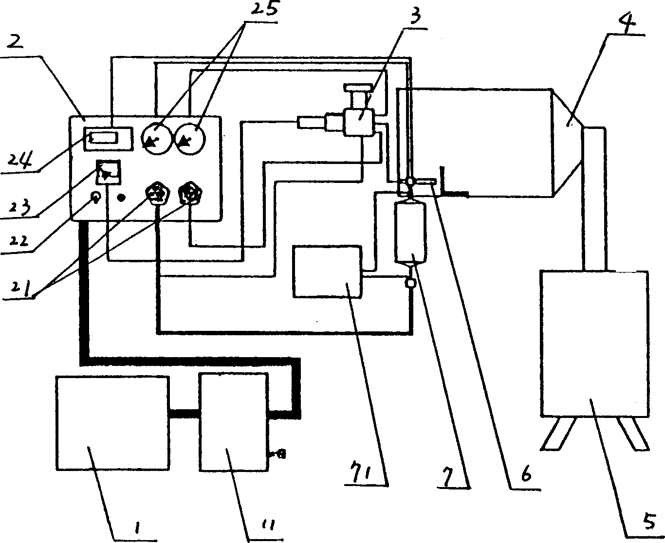
[0018] like figure 2 , 3 , 4, it is composed of a supersonic nozzle 6, a heater 7, a powder feeder 3, a spraying chamber 4, a powder recovery device 5, and a controller 2, wherein the supersonic nozzle 6 is installed at the entrance of the spraying chamber 4, and the controller 2. Connect with the pipeline of air compressor 1 with air storage tank 11, and connect with heater 7 and powder feeder 3 respectively through powder feeding switch 22 and pressure regulating switch 21. Heater 7 is equipped with heating power supply 71, one end To the supersonic nozzle 6, a powder recovery device 5 is installed at the outlet of the spraying chamber 4;

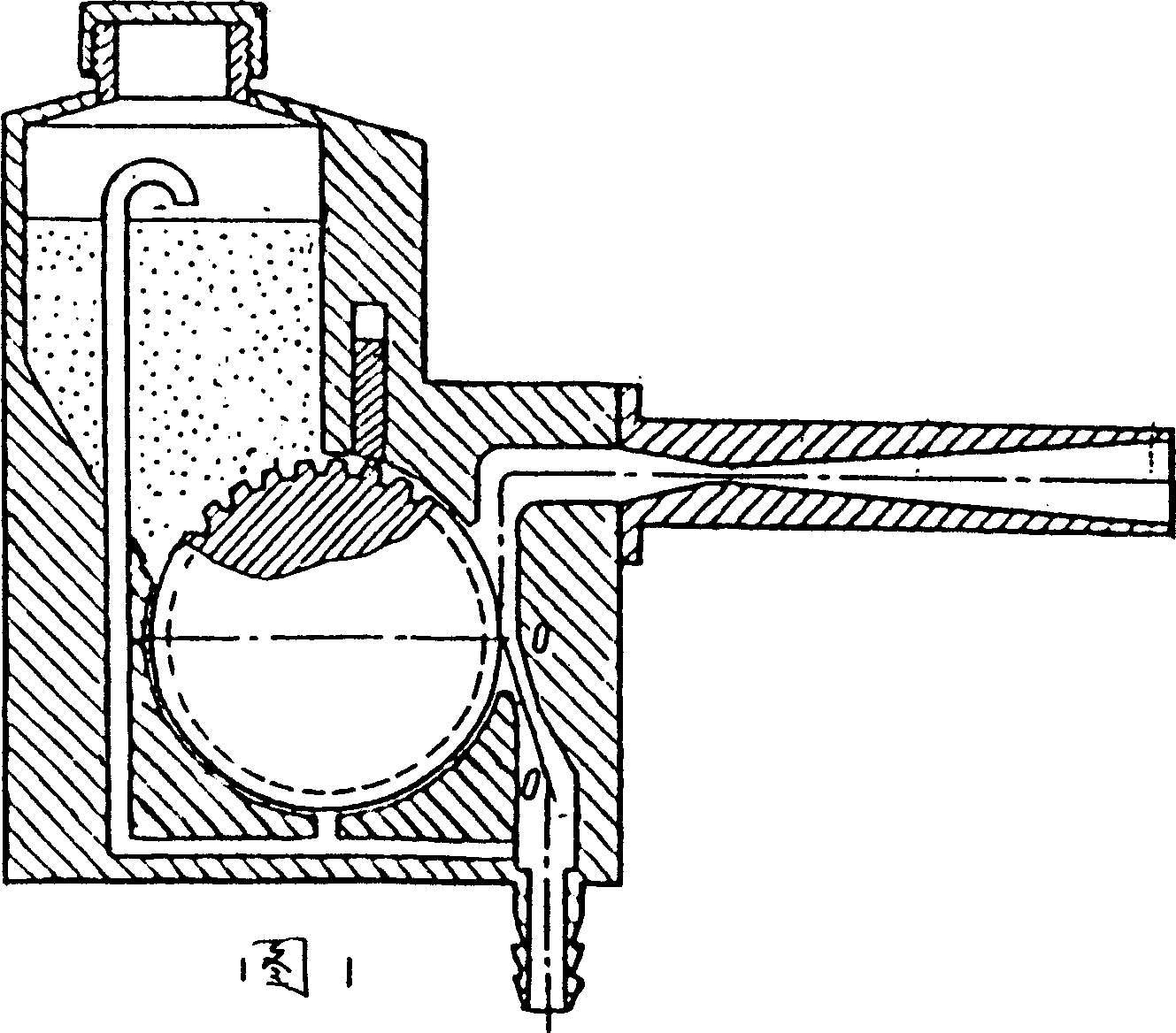
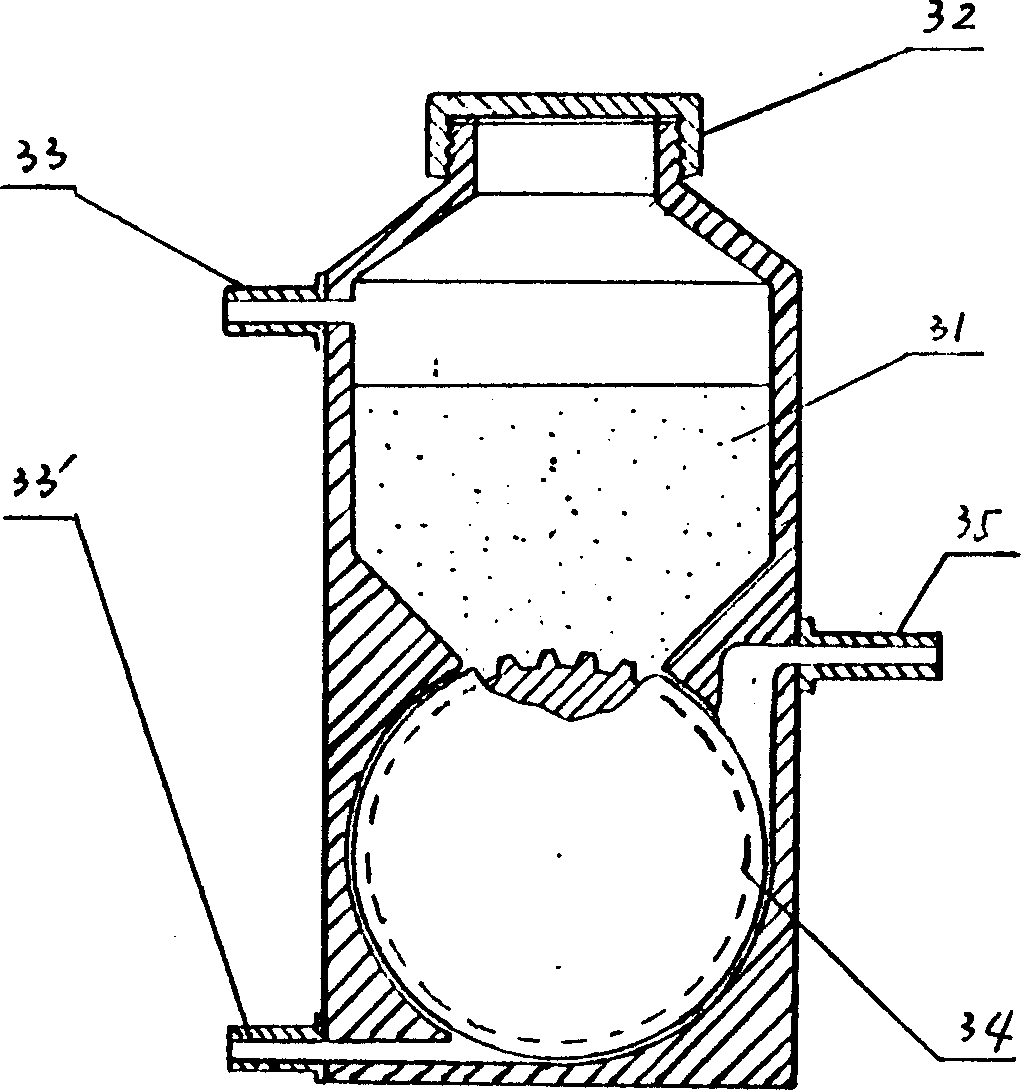
[0019] The supersonic nozzle 6 is connected to the powder feeder 3 through a pipeline, and consists of three parts: a contraction section 61, a throat 62, and an expansion section 63. The contraction section 61...


PUM

PropertyMeasurementUnit
shear strengthaaaaaaaaaa
electrical resistanceaaaaaaaaaa
thicknessaaaaaaaaaa

Abstract

The spray painter consists of ultrasonic nozzle, heater, powder feeder and other parts. The ultrasonic nozzle is mounted in the inlet of the spraying chamber, and the controller connected to the air compressor with air tank is connected via a powder feeding switch and pressure regulating switch to the heater and the powder feeder. The heater has one end connected to the ultrasonic nozzle. There is one powder recovering unit in the outlet of the spraying chamber. The ultrasonic nozzle is connected with the powder feeder and consists of three parts of contracting section, throat and expanding section. The present invention has high powder feeding efficiency, long service life and no oxidation.

Description

technical field [0001] The invention relates to surface spraying treatment of materials, in particular to a cold air power spraying device. Background technique [0002] In the existing technology, two kinds of technologies are mostly used for the surface spraying treatment of materials. One is the traditional thermal spraying technology, such as: flame spraying, arc spraying, plasma spraying, supersonic flame spraying and explosive spraying, etc. The common characteristics are Use different heat sources to heat various materials to be sprayed, such as metals, alloys, ceramics, plastics and various composite materials, to a molten or molten state, and form a "particle mist flow" with the aid of high-speed atomization of airflow to deposit on the pretreated work. The surface forms a coating that is closely combined with the substrate in a piled up shape. Since thermal spraying requires a very high temperature during the spraying process, when the flame stream leaves the nozz...

Claims


Application Information

Patent Timeline
Patent Type & Authority Applications(China)
IPC IPC(8): B05B7/14B05B17/06B05C19/00B05D1/12C23C4/12
Inventor 熊天英李铁藩吴杰金花子吴敏杰李鸣王兆玉陶杰刘芳欣陈金生
Owner INST OF METAL RESEARCH - CHINESE ACAD OF SCI
Why Eureka
Try Eureka