
Vertical slag-cooling machine

A slag cooler, vertical technology, applied in the supporting application field of fluidized fluidized coal-fired furnace, can solve the problems of high cost, large energy required, complex movement structure, etc.

Inactive Publication Date: 2003-03-19
李玉清
View PDF0 Cites 1 Cited by
  • Summary
  • Abstract
  • Description
  • Claims
  • Application Information

AI Technical Summary

Problems solved by technology

In addition to the different driving methods, they all adopt inclined installation. The main transmission power is the sliding displacement of hot slag formed in the transmission box by means of mechanical drive. The energy required is large, the movement structure is complex, relatively speaking, its wear is also large, and the cost Therefore, a completely new structural solution to completely reduce the expensive construction and operation costs of the slag cooling machine has yet to be explored.

Method used


Image

  • Vertical slag-cooling machine
  • Vertical slag-cooling machine
  • Vertical slag-cooling machine

Examples


Embodiment Construction

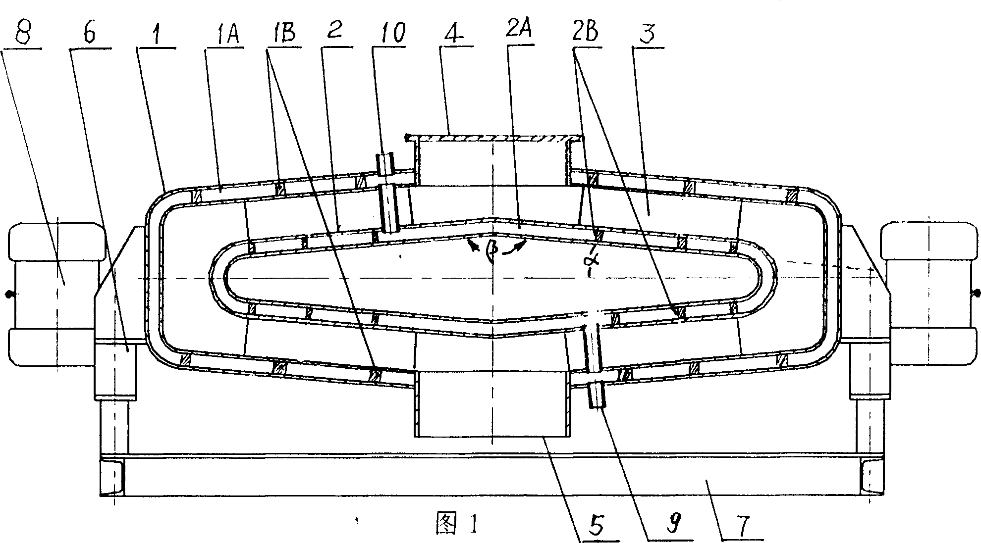
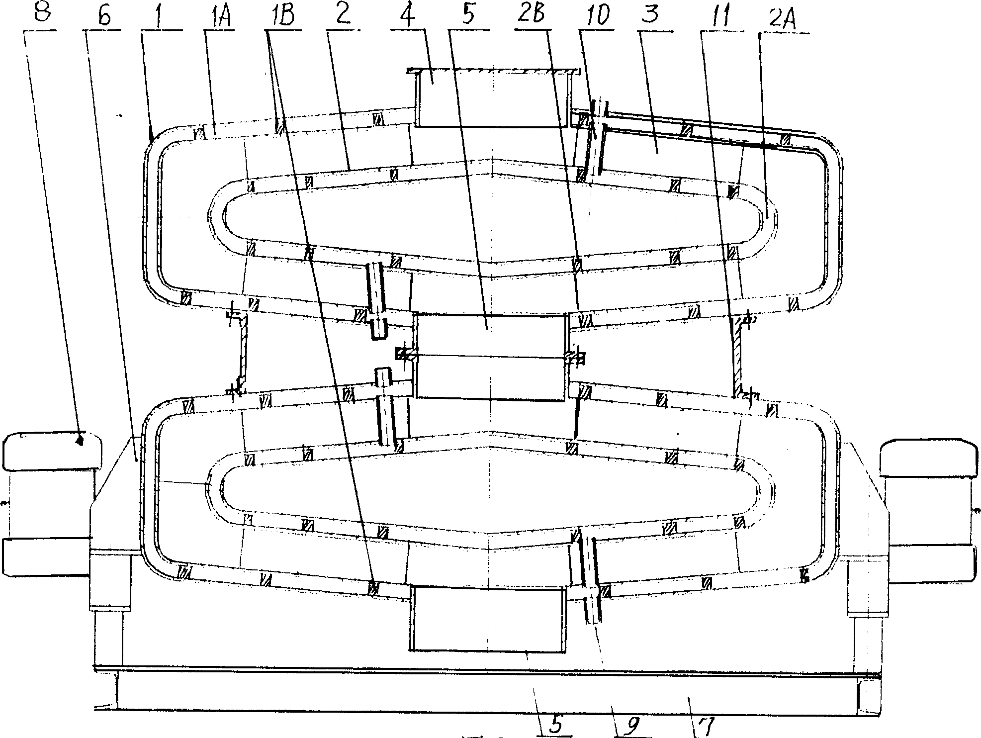
[0009] The accompanying drawings show the basic structure (Fig. 1) and series structure (Fig. figure 2 ) Two kinds of embodiments. In order to ensure the structural specification of the sandwich shell, strong resistance to deformation, and stability during operation, evenly distributed support and positioning ribs (1B, 2B) are arranged in the sandwich shell of the inner and outer boxes. The existence of these ribs makes the inner and outer shells form a whole, which not only has greater rigidity and strength, but also ensures the normal flow of circulating water in the water chamber.

[0010] The positioning support ribs 3 set up between the inner and outer boxes (1, 2) are not only for the positioning and supporting relationship between the inner and outer boxes, but also are heat-absorbing and hot slag guide plates. Therefore, its number, location, and shape have a great relationship with the working quality of the slag cooler. The simplest is the rectangular planar struct...


PUM


Abstract

The present invention is the improved design of slag-cooling machine. The improved design is one vertical structure and composite box. The composite box is sandwiched one with outer and inner layers, and the sandwiched water cavity is communicated with the heat exchanging circulating water passage. Between one outer box including cylindrical main part and upper and lower conic parts and one discus-shaped inner box, there is the conic hot slag passage. The hot slag entering the box is shifted to the slag outlet via the slight vibration.

Description

technical field [0001] The invention belongs to a special device for continuously transporting high-temperature materials and simultaneously completing heat energy exchange and recovery. It is especially suitable for matching application with boiling fluidized coal-fired furnace. Background technique [0002] Since the popularization and application of fluidized bed technology, the continuous discharge of high-temperature hot slag and the recovery of heat energy have promoted the continuous improvement of the design of the slag cooler. At present, there are three series of designs for the cold slag machine, the rotating drum type, the vibrating box type and the swing cavity type. In addition to the different driving methods, they all adopt inclined installation. The main transmission power is the sliding displacement of hot slag formed in the transmission box by means of mechanical drive. The energy required is large, the movement structure is complex, relatively speaking, ...

Claims


Application Information

Patent Timeline
IPC IPC(8): F23C10/18
Inventor 李玉清
Owner 李玉清
Features
  • Generate Ideas
  • Intellectual Property
  • Life Sciences
  • Materials
  • Tech Scout
  • Unparalleled Data Quality
  • Higher Quality Content
  • 60% Fewer Hallucinations
Learn More