Magnetron

A magnetron and magnetic pole technology, applied in the field of magnetron, can solve problems such as deterioration of magnetron oscillation efficiency

Inactive Publication Date: 2003-03-19
PANASONIC CORP
View PDF0 Cites 12 Cited by
  • Summary
  • Abstract
  • Description
  • Claims
  • Application Information

AI Technical Summary

Problems solved by technology

As a result, the conventional magnetron once placed in a low-temperature environment below -40°C has a problem that the magnetic flux density in the supply electron movement space falls below a specified value, and the oscillation efficiency of the magnetron deteriorates.

Method used


Image

  • Magnetron
  • Magnetron
  • Magnetron

Examples


Embodiment 1

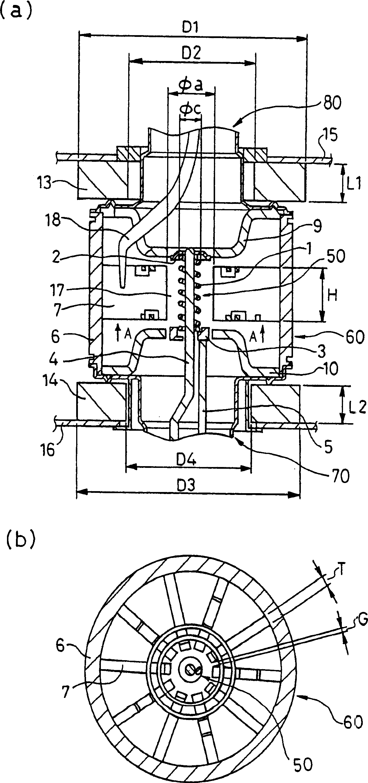
[0056] figure 1 It is an enlarged sectional view showing a main part of the magnetron according to Embodiment 1 of the present invention. figure 1 (a) is the side sectional view of the magnetron of embodiment 1, figure 1 (b) means from figure 1 (a) Cross-sectional view of the anode part and the like viewed in the direction of arrow A.

[0057] like figure 1 As shown, the cathode part 50 is arranged in the central part of the magnetron, and the anode part 60 is arranged around it. The cathode portion 50 is composed of a filament 1 and a central lead 4 and a side lead 5 connected by end caps 2 and 3 provided at both ends of the filament 1 . The center lead 4 is disposed substantially on the central axis of the coiled filament 1 . The anode part 60 is a cylindrical anode cylinder 6 arranged substantially coaxially with the filament 1, and is provided so as to protrude from the inner peripheral surface of the anode cylinder 6 to the filament 1 and arranged so that its ti...

Embodiment 2

[0079] Below, while referring to the attached Figure 1 Next, the magnetron of the second embodiment of the present invention will be described.

[0080] Figure 7 It is an enlarged cross-sectional view showing main parts of the magnetron according to Embodiment 2 of the present invention. Figure 7 (a) is the side sectional view of the magnetron of embodiment 2, Figure 7 (b) means from Figure 7 (a) Cross-sectional view of the anode part, etc. viewed from the arrow A direction.

[0081] like Figure 7 As shown, the cathode part 150 is arranged in the central part of the magnetron, and the anode part 160 is arranged around it. The cathode part 150 is composed of a filament 101 and a central lead 104 and a side lead 105 connected by end caps 102 and 103 provided at both ends of the filament 101 . The anode part 160 is formed by a cylindrical anode cylinder 106 and a plurality of blades 107 protruding from the inner peripheral surface of the anode cylinder 106 to the fila...


PUM

PropertyMeasurementUnit
diameteraaaaaaaaaa
diameteraaaaaaaaaa

Abstract

A magnetron comprising an anode portion having an anode cylinder and vanes, a cathode portion having a coil-shaped filament, magnetic poles disposed at the upper and lower ends of the filament, ring-shaped permanent magnets made of a Sr ferrite magnet containing La-Co, an input portion and an output portion. The diameter phia of the inscribed circle at the ends of the vanes constituting the anode portion is in the range of 7.5 to 8.5 mm, and the outside diameter phic of the coil-shaped filament 1 constituting the cathode portion is in the range of 3.4 to 3.6 mm.

Description

technical field [0001] The invention relates to a magnetron used in microwave application equipment such as an electronic cooker. Background technique [0002] Magnetron is an electron tube that generates microwaves. Because of its relatively high oscillation efficiency and easy output of high power, it is widely used as a microwave source for microwave application equipment including electronic cookers. [0003] Hereinafter, a conventional magnetron will be described. [0004] Figure 13 It is a sectional view of a magnetron used in an existing general electronic cooker. like Figure 13 As shown, a cathode part 250 is arranged in the central part of the magnetron, and an anode part 260 is arranged around it. The cathode part 250 is composed of a filament 201 , and a central lead 204 and a side lead 205 connected by end caps 202 and 203 provided at both ends of the filament 201 . The anode part 260 is composed of a cylindrical anode 206 and a plurality of blades 207 protr...

Claims


Application Information

Patent Timeline
Patent Type & Authority Applications(China)
IPC IPC(8): H01J23/15C23C14/34H01J23/05H01J23/10H01J23/20H01J25/50H01J25/587
CPCH01J25/587H01J23/20H01J23/15
Inventor 石井健半田贵典相贺正幸桑原渚
Owner PANASONIC CORP
Why Eureka
Try Eureka