
Automobile gas exhausting manifold branch

A technology for automobile exhaust and exhaust manifold, applied in the direction of exhaust device, air quality improvement, noise reduction device, etc., which can solve the problem of heavy weight of exhaust manifold 20, difficulty in manufacturing, shortening the overall life of exhaust manifold 20, etc. question

Inactive Publication Date: 2003-04-16
HYUNDAI MOTOR CO LTD
View PDF0 Cites 9 Cited by
  • Summary
  • Abstract
  • Description
  • Claims
  • Application Information

AI Technical Summary

Problems solved by technology

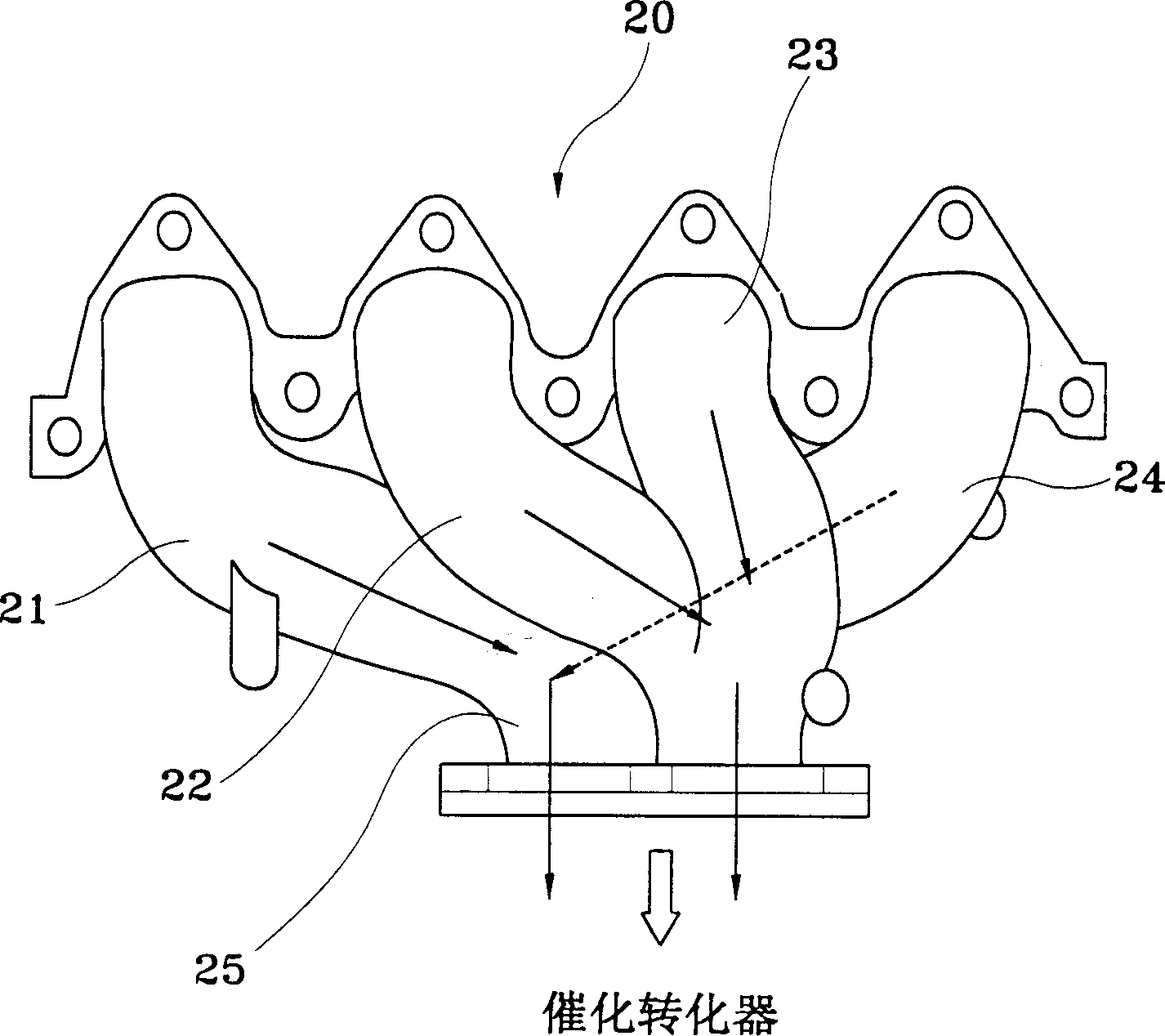
[0013] However, in this exhaust manifold 20, the first air passage 21 and the fourth air passage 24 are opposed to each other, so if the first air passage 21 and the fourth air passage 24 are too short, it is impossible to avoid the corresponding ignition. Exhaust resistance in sequence (first cylinder→third cylinder→fourth cylinder→second cylinder)
[0014] In addition, similar to the 4-1 type exhaust manifold 10, in the 4-2-1 type exhaust manifold 20, the intervals between the air passages 21, 22, 23 and 24 are all narrow, and as a result, because of thermal stress , cracks often occur in the exhaust confluence portion, which in turn shortens the overall life of the exhaust manifold 20
[0015] Also, the 4-2-1 exhaust manifold 20 is structurally more complex than the 4-1 exhaust manifold 10
It is therefore more difficult to manufacture and the weight of the exhaust manifold 20 will be greater

Method used


Image

  • Automobile gas exhausting manifold branch
  • Automobile gas exhausting manifold branch
  • Automobile gas exhausting manifold branch

Examples


Embodiment Construction

[0024] Such as Figure 5 to Figure 7 As shown, in an exhaust manifold 30 according to the present invention, the first, second, third and fourth air passages 31, 32, 33 and 34 are connected to the exhaust converging portion 35 at constant intervals.

[0025] The first air passage 31 and the fourth air passage 34 are respectively connected to both sides of the exhaust confluence part 35 at the same inclination angle. The second air passage 32 and the third air passage 33 located between the first and fourth air passages 31 and 34 are integrated in a “Y” shape, and then the combined body is connected to the exhaust confluence part 35 .

[0026] The cross-sectional areas of the first, second, third and fourth air passages 31, 32, 33 and 34 are constant throughout their length, but these air passages are connected to the exhaust confluence part, and their The cross-sectional area is expanded to a predetermined size.

[0027] see Figure 5 to Figure 7 , wherein the letter M repr...


PUM


Abstract

An exhaust manifold for vehicle is disclosed. First and fourth runners among a plurality of runners connected to cylinders of an engine are respectively connected to sides of a gas confluence part. Second and third runners disposed between the first and fourth runners are joined together integrally before being connected to the gas confluence part.

Description

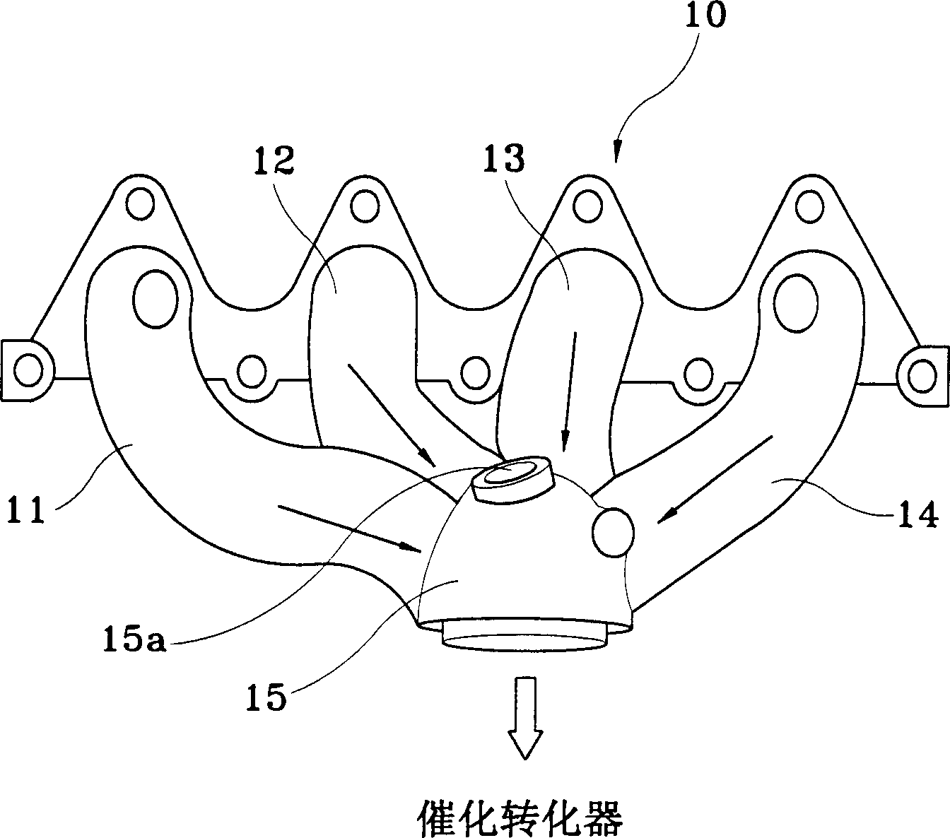
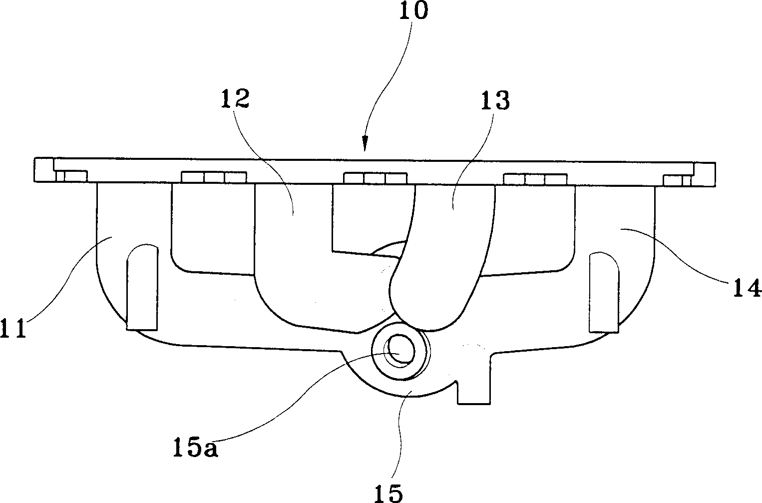
technical field [0001] The invention relates to an automobile exhaust manifold, in particular to an automobile exhaust manifold capable of uniformly distributing exhaust gas passing through a catalytic converter and preventing various cracks caused by thermal stress. Background technique [0002] In general, an exhaust manifold refers to a component that gathers the exhaust gas from each cylinder of the engine and directs the exhaust gas flow to the exhaust pipe. On a four-cylinder engine, four ports are typically used, one type of port is connected directly to the exhaust manifold, and the other type of port is divided into two pairs connected to the exhaust manifold. [0003] The former type (four airways connected directly) is usually called 4-1 type, and its structure is as follows figure 1 , figure 2 shown. [0004] Such as figure 1 , figure 2 As shown, the exhaust manifold 10 is composed of four air passages 11, 12, 13, 14 connected to the exhaust confluence par...

Claims


Application Information

Patent Timeline
Patent Type & Authority Applications(China)
IPC IPC(8): F01N3/28F01N13/10
CPCF01N13/10F01N3/28Y02A50/20
Inventor 金兴哲
Owner HYUNDAI MOTOR CO LTD
Learn More