
Phase-compensated impedance converter

A gyrator and integrated circuit technology, applied in the field of phase compensation gyrators, integrators, and S components, can solve problems such as differential sensitivity characteristics, gyrator unit unreliability, etc.

Inactive Publication Date: 2003-04-23
OPTIS WIRELESS TECH LLC
View PDF2 Cites 7 Cited by
  • Summary
  • Abstract
  • Description
  • Claims
  • Application Information

AI Technical Summary

Problems solved by technology

[0014] Additionally, applicants believe that no complex active high frequency continuous-time chip scale MOS filter has been fabricated due to the unreliability of the gyrator unit
The filters that have been manufactured are very simple, limited to low-order filters or cascaded low-order filters (with poor sensitivity characteristics) or more complex low-frequency filters

Method used


Image

  • Phase-compensated impedance converter
  • Phase-compensated impedance converter
  • Phase-compensated impedance converter

Examples


Embodiment Construction

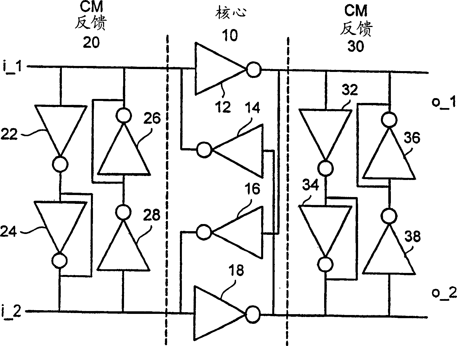
[0027] This application has figure 2 Applicants' invention has been described in the context of a gyrator in a cross-connect configuration as shown, but it should be understood that the invention is not limited to such a context. For example, the analysis presented in this description applies equally to integrators, and thus also to filters formed of integrators. Also, this description assumes the use of conventional CMOS inverter ICs because they are readily available, but embodiments of applicant's invention can also use other types of components, such as bipolar and field effect (unipolar) components as well as bipolar Type CMOS (BiCMOS) components.

[0028] Applicant's invention is based on the recognition that conventional filter first-order stability analysis, which assumes fully on transconductance for MOS-like components, is insufficient. Some corollaries of this realization are described in Patent Application No. 9916808.0 "Integrated Circuits", incorporated by ref...


PUM


Abstract

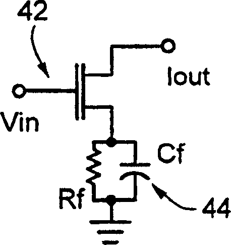
Integrated circuits, for example, gyrator circuits include transistors that are preferably MOS devices and that are provided with series feedback networks, which compensate for the effects of channel delay in the MOS devices.

Description

Background of the invention [0001] The present invention relates to electronic impedance converter circuits, in particular to inverters or gyrators, and more particularly to phase compensated gyrators and integrators. [0002] One of the advantages of electronic integrated circuits (ICs) is their small size, so ICs are commonly used in hand-held or other devices, but some circuits require some components that are difficult to integrate. In particular, it is difficult to integrate passive inductances larger than a few nanohenries (nH). Thus, for example, chip-scale passive signal filters are generally limited to resistor-capacitor (RC) filters, unless filters are designed for very high frequencies, where an inductance (coil) of a few nH is effective. [0003] In communications and electronics, a filter usually refers to hardware or software that selectively passes one component of a signal while removing or minimizing other components. For example, a filter in a telecommunica...

Claims


Application Information

Patent Timeline
Patent Type & Authority Applications(China)
IPC IPC(8): H03H11/42
CPCH03H11/42
Inventor S·马特蒂森
Owner OPTIS WIRELESS TECH LLC
Learn More