Hydraulic oscillating machine

A full hydraulic and hydraulic cylinder technology, applied in the field of full hydraulic oscillators, can solve the problems of high failure rate, high cost, complex structure, etc., and achieve the effects of low cost, long service life and reliable operation

Inactive Publication Date: 2003-05-14
BEIHANG UNIV
View PDF0 Cites 6 Cited by
  • Summary
  • Abstract
  • Description
  • Claims
  • Application Information

AI Technical Summary

Problems solved by technology

[0003] Traditional hydraulic technology realizes the reciprocating reversing movement of the hydraulic cylinder, usually using electromagnetic reversing valves (including electro-hydraulic reversing valves) and motorized reversing valves, which have disadvantages such as complex structure, high failure rate, and high cost.

Method used


Image

  • Hydraulic oscillating machine
  • Hydraulic oscillating machine
  • Hydraulic oscillating machine

Examples


Embodiment Construction

[0014] The present invention will be further described below in conjunction with the accompanying drawings and embodiments.

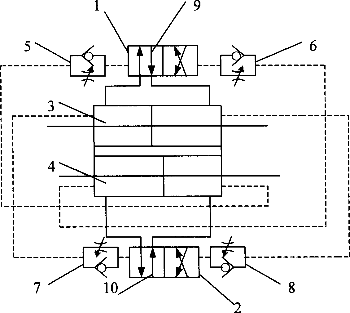
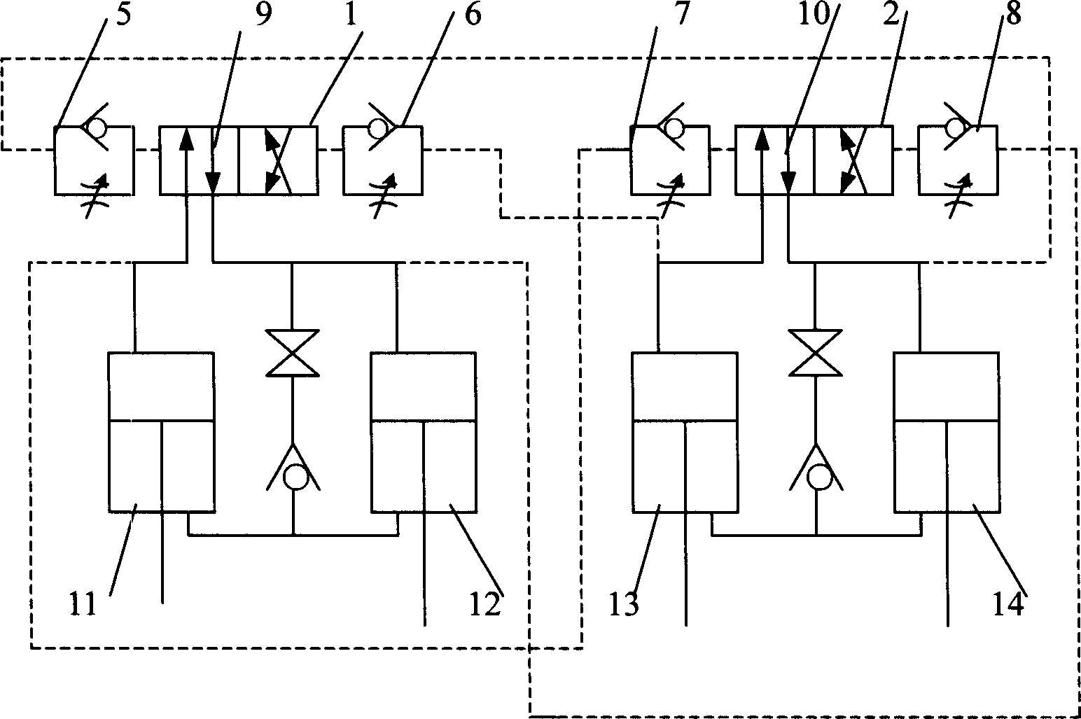
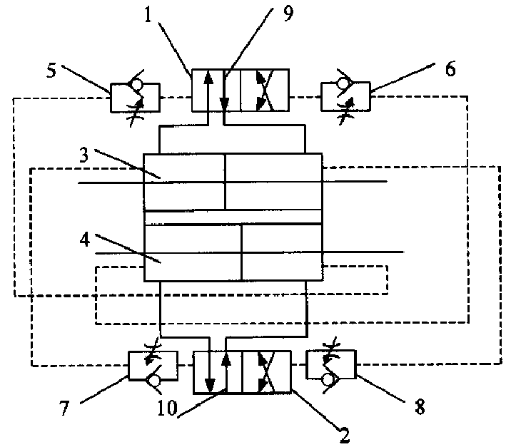
[0015] See figure 1 As shown, the full hydraulic oscillator of the present invention consists of two two-position four-way hydraulic reversing valves 1 and 2, two double-rod hydraulic cylinders 3 and 4, and four one-way throttle valves 5, 6, 7 and 8 constitute. It is improved for the hydraulic circuit, omitting the oil source part.

[0016] In the present invention, the four-way hydraulic reversing valve 1 controls the movement of the hydraulic cylinder 3 , and the four-way hydraulic reversing valve 2 controls the movement of the hydraulic cylinder 4 . The four one-way throttle valves are respectively connected to the control ports of the two hydraulic reversing valves, and the reversing time of the reversing valves is controlled by way of outlet throttling. The control ports at both ends of the four-way hydraulic reversing valve 1 are connected to t...


PUM


Abstract

The hydraulic oscillating machine includes a hydraulic loop comprising change-over valve, throttle valve and hydraulic cylinder. The hydraulic change-over valve controls the motion of the hydraulic cylinder; the single-way throttle valve is connected to the control port of the hydraulic chagne-over valve to control the change-over time of the change-over valve in outlet throttle mode; and the twocavities of the hydraulic cylinder are connected via the single-way throttle valve to the two control ports of the hydraulic change-over separately. The pressure oil inlet of the hydraulic change-over valve is connected to the oil source parallel. On starting hydraulic pump to provide pressure oil, the hydraulic cylinder will move alternately, the motion speed of the hydraulic cylinder is regulated by the variable hydraulic pump of oil source and the stroke of the hydraulic cylinder is regulated by the single-way throttle valve.

Description

technical field [0001] The invention relates to an oscillating machine, in particular to an all-hydraulic oscillating machine with full-hydraulic drive to realize continuous reciprocating linear motion. Background technique [0002] Water injection (or polymer injection) pumps in oil fields need to provide power devices, which are mostly realized by mechanical transmission. This kind of crank-link mechanical transmission has problems such as fast stroke times, large vibration, large wear of machine parts, and inconvenient adjustment of working parameters. Using hydraulic transmission to drive the water injection pump can achieve large strokes and small strokes to overcome the problems of mechanical transmission. [0003] Traditional hydraulic technology realizes the reciprocating reversing movement of hydraulic cylinders, usually using electromagnetic reversing valves (including electro-hydraulic reversing valves) and motorized reversing valves, which...

Claims


Application Information

Patent Timeline
Patent Type & Authority Applications(China)
IPC IPC(8): F04B37/00F15B13/02
Inventor 曾贤启
Owner BEIHANG UNIV
Why Eureka
Try Eureka