Driving device for vibration type regulator

A driving device and regulator technology, applied in the direction of fluid, electromechanical device, AC motor control, etc. using vibration, can solve the problems of many terminals, difficult to realize the integrated circuit for driving, etc., and achieve the effect of easy absorption

Inactive Publication Date: 2003-05-21
TEIKOKU TSUSHIN IND CO LTD +1
View PDF3 Cites 4 Cited by
  • Summary
  • Abstract
  • Description
  • Claims
  • Application Information

AI Technical Summary

Problems solved by technology

[0008] Also, in claim 8 of Japanese Patent Publication No. 2001-128487, it is mentioned that "the vibration-type linear adjustment described in any one of claims 1 to 7 is characterized in that the natural vibration number is obtained in a state where the supply of current to the coil is stopped. device"

Method used


Image

  • Driving device for vibration type regulator
  • Driving device for vibration type regulator
  • Driving device for vibration type regulator

Examples


Embodiment Construction

[0027] Below we describe the present invention in detail according to accompanying drawing. First, we describe the drive circuit of a typical vibration regulator.

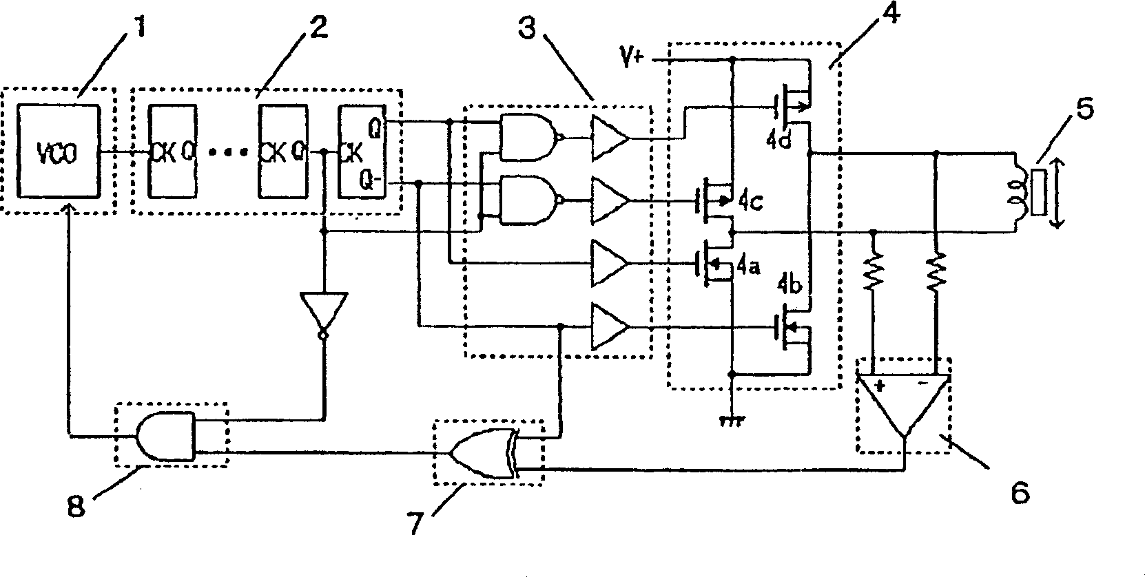
[0028] figure 1 is a block diagram of a representative embodiment of the invention. The output terminal of the control oscillator 1 is connected to the frequency divider 2, and the final Q output terminal and the Q- output terminal of the frequency divider 2 are connected to the waveform shaping circuit 3, through the buffer in the waveform shaping circuit 3 and the drive circuit 4 Gate connection of each MOS transistor. However, if the drive capability of the NAND gate of the waveform shaping circuit 3 and the final Q output terminal and Q- output terminal of the frequency divider 2 is high, the above-mentioned buffer is not necessarily required.

[0029] The drains of the interconnected MOS transistors 4a, 4c and the MOS transistors 4b, 4d are respectively connected to drive coil terminals of the vibration re...


PUM


Abstract

The present invention actualizes a drive suited to accummulation, capable of attaining effective drive near the resonance frequency of an oscillating actuator. This drive for oscillating type actuator employs a FLL (Frequency Locked Loop) which detects electromotive force generated at a driving winding by mechanical oscillation during down period of the driving current of an oscillating type actuator, controls oscillating frequency in accordance with the relative time ratio of positive and negative polarities, and draws driving frequency into a section nearer to the self-resonance frequency of the oscillating type actuator.

Description

technical field [0001] The present invention relates to a vibrator made of permanent magnets or electromagnets, a stator made of electromagnets or permanent magnets, and a drive device for a vibrating regulator made of elastic bodies that support the vibrator, and is particularly suitable for the usual work as a portable phone (Japanese : Mana) mode used in the vibrator vibration regulator drive device. Background technique [0002] There are many cases of eccentric motors for vibrators used in the normal operation (Japanese: マナ) mode of existing mobile phones, but in recent years, mobile phones using both resonance and linear vibration regulators without bearings have been used. The vibrator is eye-catching. A driving device for generating a driving signal using the self-resonant frequency of such a vibration-type regulator includes DRIVING CIRCUIT FOR OSCILLATORY ACTUATOR (drive circuit for a vibration-type regulator) of US Patent No. 6,133,701. This is how Figure 13 Sh...

Claims


Application Information

Patent Timeline
IPC IPC(8): B06B1/04H02K33/04H02P25/02
CPCH02P25/027H02P25/032
Inventor 日下部博巳
Owner TEIKOKU TSUSHIN IND CO LTD
Why Eureka
Try Eureka