Motor rotor and its mfg. method, motor, brushless motor, compressor, refrigerator and air conditioner

A technology for electric motors and induction motors, which is applied in the manufacture of motor generators, asynchronous induction motors, synchronous motors for single-phase current, etc. Small, reduced magnetoresistance, reduced pressure loss effect

Inactive Publication Date: 2003-05-28
MITSUBISHI ELECTRIC CORP
View PDF0 Cites 18 Cited by
  • Summary
  • Abstract
  • Description
  • Claims
  • Application Information

AI Technical Summary

Problems solved by technology

When using a synchronous induction motor in which the slit of the rotor that generates reluctance torque is filled with aluminum and the ends of the rotor are short-circuited with end rings, it is necessary to provide a vent hole in a hermetic compressor. The rotor is provided with slits, and the slits are filled with aluminum, so it is difficult to form holes in the slits
Since the part without the slit is the part through which the magnetic flux passes, there is a problem that the reluctance increases when the hole is opened, and the output power decreases, resulting in a decrease in efficiency.

Method used


Image

  • Motor rotor and its mfg. method, motor, brushless motor, compressor, refrigerator and air conditioner
  • Motor rotor and its mfg. method, motor, brushless motor, compressor, refrigerator and air conditioner
  • Motor rotor and its mfg. method, motor, brushless motor, compressor, refrigerator and air conditioner

Examples


Embodiment approach 1

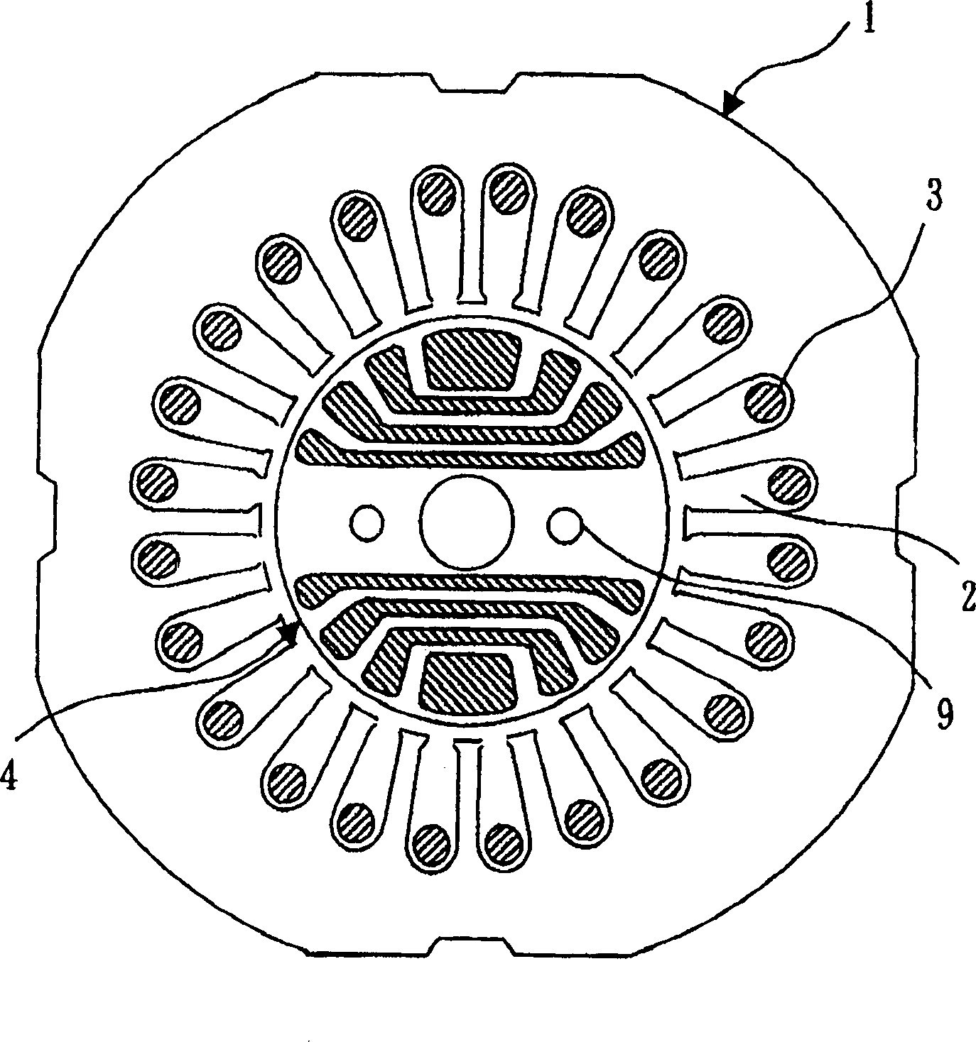
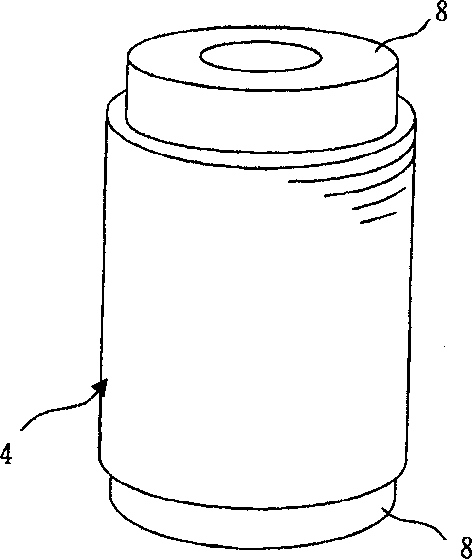
[0069] Figure 1 to Figure 4 is a diagram showing Embodiment 1, figure 1 It is a cross-sectional view of the stator and rotor of a synchronous induction motor, figure 2 is a perspective view of the rotor of a synchronous induction motor, image 3 is a cross-sectional view of the rotor of a synchronous induction motor, Figure 4 It is a cross-sectional view of a rotor of a synchronous induction motor in which a non-filled portion is provided in a slit.

[0070] exist Figure 1 ~ Figure 3 Among them, 1 is a stator of a synchronous induction motor, and coils 3 provided in a plurality of slots 2 on the inner diameter side of the stator 1 are wound so as to give a rotating magnetic field for rotating the rotor 4 . The rotor 4 is arranged inside the stator 1, and the slot part 5 for generating the induction torque and the slit part 6 for generating the reluctance torque are integrally provided on the rotor 4, and inside the slot part 5 and the slit part 6 The aluminum 7 that c...

Embodiment approach 2

[0082] 5 is a diagram showing Embodiment 2, and is a cross-sectional view of a rotor of a synchronous induction motor. As shown in the figure, the non-filled portion 10 is provided on the slit portion 6 closest to the center of the rotor 4 .

[0083] With this structure, since the amount of aluminum of the end ring 8 that functions as the rotor of the induction motor is not reduced, the secondary side resistance of the rotor can be reduced, and the torque of the induction motor as a region where the slip ratio is small can be increased. After the motor starts, it can stably enter synchronous operation.

[0084] In addition, when a synchronous induction motor is used in a hermetic compressor, since the peripheral speed generated by the rotation of the non-filling portion 10 functioning as a vent hole is small when the non-filling portion 10 is located on the rotor center side, it is possible to reduce the speed of passing through the non-filling portion 10. The pressure loss o...

Embodiment approach 3

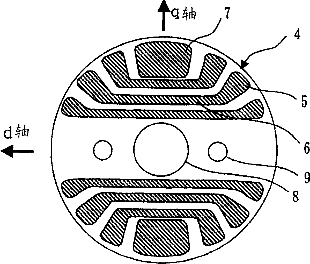
[0087] Figure 6 It is a diagram showing Embodiment 3, and is a cross-sectional view of a rotor of a synchronous induction motor. As shown in the figure, two elliptical vent holes 9 are provided in the radial direction of the d-axis, and the elliptical holes are arranged as long holes along the radial direction of the d-axis.

[0088] With this structure, the increase in the reluctance in the d-axis direction of the portion imparting the reluctance torque due to the provision of the vent hole 9 can be greatly suppressed, and the decrease in the stator coil inductance Ld viewed from the d-axis side can be greatly suppressed, so , Obtain a synchronous induction motor with increased reluctance torque and high efficiency. In addition, since torque can be generated using a more compact and narrow rotor, it can be miniaturized and cost reduced.

[0089] In the above-mentioned embodiment, the case where the elliptical air hole 9 is provided has been described, but it is not limited...


PUM


Abstract

To provide a rotor for synchronous induction motor capable of preventing the lowering of output or efficiency due to increasing magnetic resistance even if a gas venting hole is formed for using a hermetic compressor. This rotor includes slots for generating induction torque and slits for generating reluctance torque. The slot and the slits are filled with aluminum. The filling aluminum is shorted by end ring at both ends of the rotor, and a non-filling section axially passed through the slit and not filled with aluminum is provided.

Description

technical field [0001] The present invention mainly relates to a vent hole structure of a rotor of a synchronous induction motor used in a hermetic compressor or the like, which is started by induction torque and synchronously operated by reluctance torque. Background technique [0002] The rotor of a motor used in a hermetic compressor is provided with vent holes in order to produce a hermetic compressor with no pressure loss and high efficiency for better passage of refrigerant gas, as described in Publication No. 64-36581. The types of motors are induction motors and DC brushless motors with permanent magnets as rotors. [0003] In addition, as described in Publication No. 64-36581, an oil shielding plate is installed on the vent hole outlet of the rotor to reduce the circulation of lubricating oil to the refrigerant circuit of the hermetic compressor in which refrigerant gas is mixed in and circulated. There is no such thing as a hermetic compressor Oil cut-off, improve...

Claims


Application Information

Patent Timeline
Patent Type & Authority Applications(China)
IPC IPC(8): F04B39/00H02K1/22H02K1/32H02K15/00H02K15/02H02K17/16H02K19/06H02K19/10H02K29/00
CPCH02K1/22H02K17/165H02K1/246H02K1/32H02K15/0012
Inventor 川口仁泷田芳雄吉野勇人
Owner MITSUBISHI ELECTRIC CORP
Why Eureka
Try Eureka