Air bag inflating mouthpiece device

A technique of inflating tubes and nozzles, applied in the field of dunnage airbags, which can solve the problems of high manufacturing cost, large number of parts, inflatable fixtures or devices 14 that cannot be reliably seated or attached

Inactive Publication Date: 2003-07-02
ILLINOIS TOOL WORKS INC
View PDF1 Cites 0 Cited by
  • Summary
  • Abstract
  • Description
  • Claims
  • Application Information

AI Technical Summary

Problems solved by technology

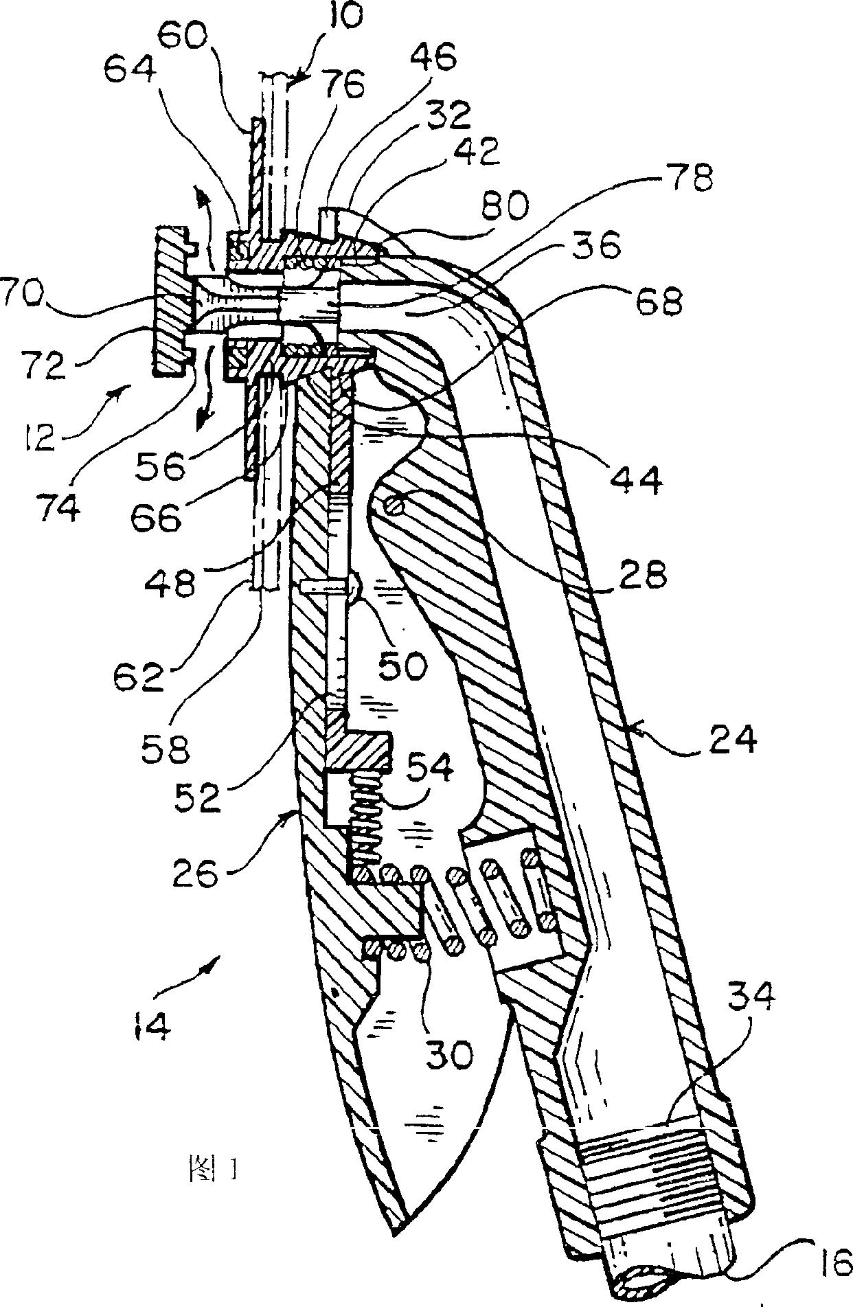
[0006] While it has been mentioned and briefly described above that the operation of the inflatable fixture or device 14 is feasible and reliable, and therefore commercially successful, it is relatively expensive to manufacture due to its high number of parts
In addition, it should be noted that the working cooperation of the inflation fixture or device 14 with the air bag inflation valve 12 is sometimes difficult to achieve because there is no effective positioning of the free end 80 of the positioning valve body 56 in the correct position relative to the nozzle head 42, The nozzle head 42 can freely enter the free end 80 of the valve body 56, so that the position that engages with the end 78 of the valve stem 70 limits the stop or stop.
If the nozzle tip 42 is not properly coaxially aligned with the free end 80 of the valve body 56, the peripheral portion of the nozzle tip 42 will engage the peripheral portion of the free end 80 of the valve body 56 and the nozzle tip 42 will not be properly positioned at It is equally important that the free end 80 of the valve body 56 is properly engaged with the end portion 78 of the valve stem 70, the inflatable clamp or device 14 will not be able to sit or be attached to the valve body 56 reliably and thus cannot be easily Realize the normal inflation of the airbag

Method used


Image

  • Air bag inflating mouthpiece device
  • Air bag inflating mouthpiece device
  • Air bag inflating mouthpiece device

Examples


Embodiment Construction

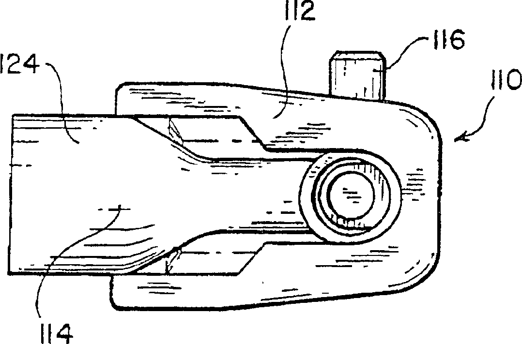
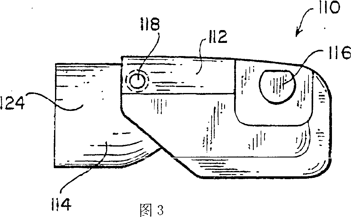
[0028] See now the attached drawings, especially the figure 2 and 3, which show a new and improved air bag inflation nozzle assembly, generally designated 110, constructed in accordance with the teachings and principles of the present invention. The structure of the airbag inflation nozzle assembly 110 is relatively simple because it basically only includes three working parts, namely an airbag inflation apparatus frame 112, an airbag inflation apparatus nozzle piece 114, and a cam lock button 116. The nozzle member 114 is mounted on the frame 112 by a pivot pin 118 so that (as will become clearer later) when the nozzle member 114 is mounted on the frame 112, the nozzle member 114 can be positioned relative to the tube of the air bag inflation valve assembly 122. A first "unengaged" and "unlatched" position (as shown in FIG. 11 ) of the tubular inflation valve body member 120 and a second "engaged" and "engaged" position of the tubular inflation valve body member 120 relative ...


PUM


Abstract

An airbag inflation nozzle assembly mating with an inflatable cargo airbag comprises a housing, and an inflation nozzle member, having an inflation nozzle tip, pivotally mounted within the housing between a first position, and a second position. A transversely oriented ramming button is movably mounted upon the housing between an UNLOCKED position so as to permit the inflation nozzle member to be moved to the first fluidically disengaged position with respect to the valve assembly, and a LOCKED position which forces the inflation nozzle member to be moved to the second fluidically engaged position with respect to the valve assembly. The housing further comprises a pair of oppositely disposed side rails upon which a valve body portion of the valve assembly can be slidably supported as the housing of the inflation nozzle assembly is being operatively mated with the valve assembly, and an end wall flange portion for engaging a valve body member of the valve assembly so as to ensure coaxial alignment of the inflation nozzle tip with the inflation valve stem.

Description

technical field [0001] This invention relates generally to dunnage airbags, and more particularly to a new and improved inflation nozzle fixture or device for inflating an inflatable liner placed inside a dunnage airbag, while the dunnage airbag It is then used to secure goods in, for example, cargo holds in railroad cars, aircraft, ships, truck trailers, or the like. Background technique [0002] In the cargo transportation industry, the dunnage airbag is used as a simple and convenient means for fixing cargo in, for example, train carriages, ships, airplanes, and load trailers. Such dunnage airbags usually include an inflatable inner bladder placed in an outer bag made of multiple layers of paper. The structure and size of the airbag are usually such that it can be easily inserted into the gap between the goods separated from each other, or between a specific cargo and the side wall of the cargo container or cargo hold. After the airbag is inflated, the airbag expands to ...

Claims


Application Information

Patent Timeline
Patent Type & Authority Applications(China)
IPC IPC(8): B65D81/07B60P7/06F04B33/00F16L37/12F16L37/26
CPCF16L37/12B60P7/065F16L37/26
Inventor 约翰J.豪利特.JR托马斯C.基南
Owner ILLINOIS TOOL WORKS INC
Why Eureka
Try Eureka