Suspension type self vibration damping difference flow sensor

A flow sensor, suspended technology, applied in the field of flow sensors, can solve the problems of limited ability to resist pipeline vibration, large noise mixed in the output signal, weak anti-interference ability of flow sensors, etc., to achieve a large range, strong anti-interference, The effect of high reliability

Inactive Publication Date: 2003-07-23
ZHEJIANG UNIV
View PDF0 Cites 2 Cited by
  • Summary
  • Abstract
  • Description
  • Claims
  • Application Information

AI Technical Summary

Problems solved by technology

However, the detection elements of these sensors are fixed on the pipe wall, and the ability to resist pipe vibration is limited.
In addition, for the interference of fluid vibration, when the vibration direction of the vibration noise is parallel to the vibration direction of the measured frequency signal (that is, vibration in the same direction), the anti-interference ability of these flow sensors is relatively weak, and the output signal will be mixed with a lot of noise.

Method used


Image

  • Suspension type self vibration damping difference flow sensor
  • Suspension type self vibration damping difference flow sensor
  • Suspension type self vibration damping difference flow sensor

Examples


Embodiment Construction

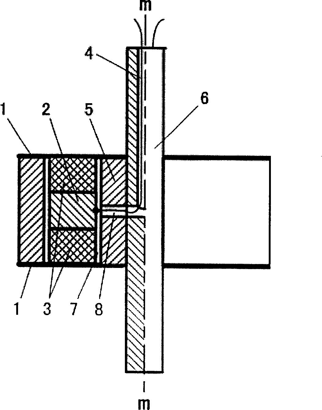
[0009] refer to figure 1 , the suspended self-damping flow sensor includes detection units symmetrically fixed on both sides of the plate 6, each detection unit includes a housing 5, in order to obtain a more stable signal, a semi-cylindrical housing is generally used, and the housing 5 has a shape parallel to the axis of the plate m-m parallel through hole 7, the through hole 7 is connected with the axial outlet hole 4 of the plate by a channel 8, the two ends of the through hole 7 are respectively sealed by elastic diaphragms 1, and there are two piezoelectric ceramic sheets 3 in the through hole , the size, mass and sensitivity coefficient of the two piezoelectric ceramic sheets are the same, one end of the two piezoelectric ceramic sheets is welded to the elastic diaphragm 1 respectively, and the other end is welded to the metal block 2 arranged between the piezoelectric ceramic sheets . In this way, the metal block 2 and the two piezoelectric ceramic sheets 3 form a rigi...


PUM


Abstract

The sensor includes the detection units fixed on the two sides of the flat plate symmetrically. Each detection unit includes the body case possessing the through holes parallel to the axis m-m of theflat plate. The channel connects the through hole and the axis out hole. The elastic membranes seal the two ends of the through hole. There are two piezoelectric ceramic sheets in the through hole. One end of each ceramic sheet is fixed on the elastic membrane and the other ends of fixed on the metal block between the ceramic sheets. There is the gap between the periphery of the ceramic sheets, the metal block and the wall of the through hole. The lead wire of the metal block via the channel and through the axial out hole of the plate is leaded out.

Description

technical field [0001] The present invention relates to flow sensors, especially self-damping differential flow sensors. Background technique [0002] In the late 1960s, new instruments that applied the principle of fluid vibration to measure flow appeared successively. For example, vortex flowmeters, jet flowmeters, and vortex precession flowmeters all belong to liquid vibration flowmeters. They pass heat-sensitive, strain, Flow sensors with detection methods such as capacitance and ultrasonic waves can detect fluid vibration frequency signals that are proportional to volume flow. For vibrating flow sensors, the vibration problem is an important indicator to measure the industrial application of a vibrating flow meter. Vibration in industry is ubiquitous, such as speed pulsation and fluid oscillation in fluid turbulence, and random factors such as industrial pipeline vibration, valve opening and closing, and valve core vibration, which will cause ...

Claims


Application Information

Patent Timeline
Patent Type & Authority Applications(China)
IPC IPC(8): G01F1/32
Inventor 宋开臣张圣宾
Owner ZHEJIANG UNIV
Why Eureka
Try Eureka