Infrared ray touch device with high resolutions

An infrared and capture device technology, applied in program control design, instruments, electrical digital data processing, etc., can solve the problem that the minimum interceptor cannot be smaller than the size of the receiving tube, etc., and achieves the advantages of circuit board wiring, saving driving circuits, and simple production. the effect of

Inactive Publication Date: 2003-07-23
贺伟
View PDF3 Cites 13 Cited by
  • Summary
  • Abstract
  • Description
  • Claims
  • Application Information

AI Technical Summary

Problems solved by technology

[0004] To completely solve the resolution problem of infrared touch devices, it is not only to improve the click resolution of its touch commands, but more importantly, to increase the resolution of infrared capture to be able to smoothly and accurately capture and process handwritten characters, drawings, etc. Even can be applied in the TABLET PC of Microsoft's window system WINDOW XP, or in products such as intelligent display, therefore find out a high precision, practical method is urgently needed, also is one of main purpose of the present invention, besides In addition, another main purpose of the present invention is to solve the problem that the smallest interceptor cannot be smaller than the size of the receiving tube and realize the coordinate capture, identification, trajectory reproduction and storage of the moving target trajectory

Method used

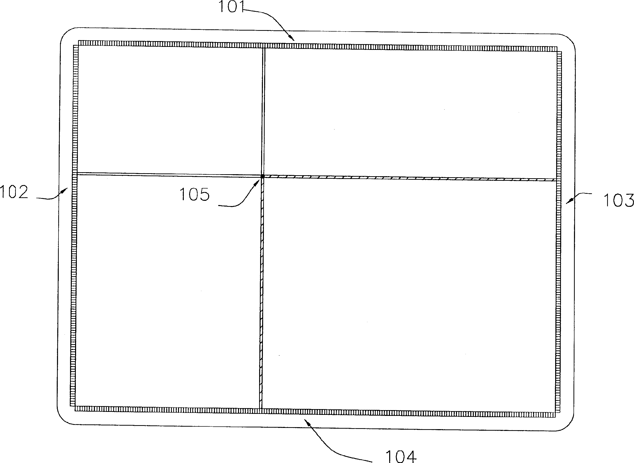
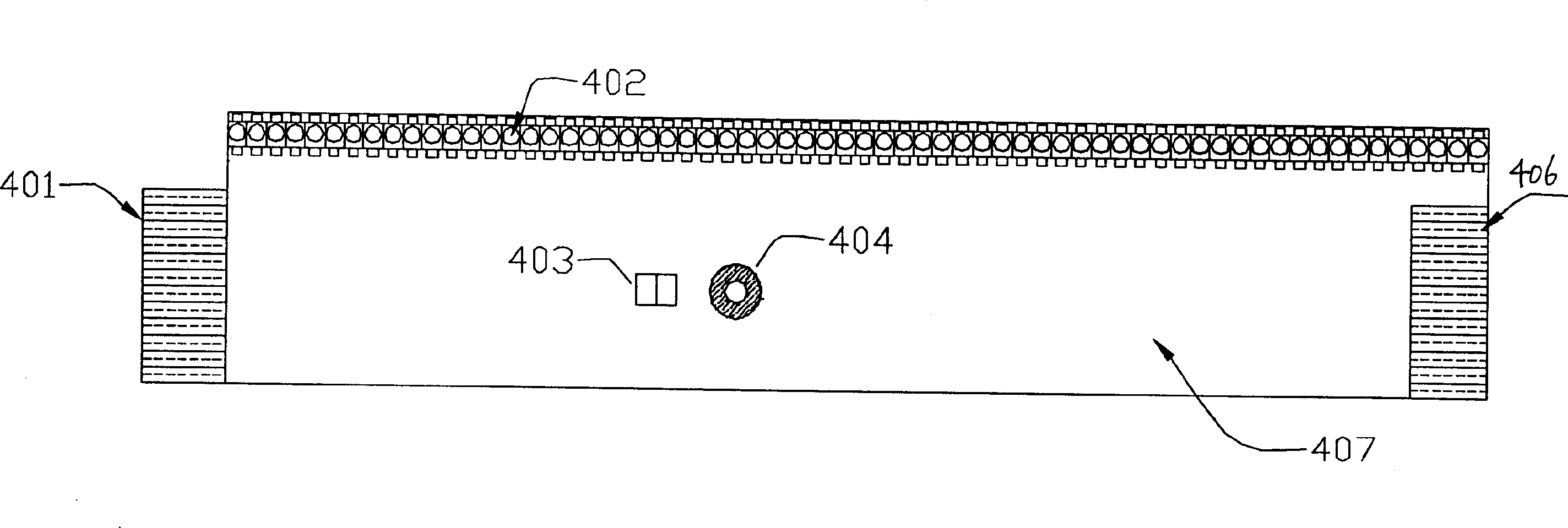

Image

  • Infrared ray touch device with high resolutions
  • Infrared ray touch device with high resolutions
  • Infrared ray touch device with high resolutions

Examples


Embodiment Construction

[0026] In order to improve the resolution captured by infrared scanning, the present invention establishes a model based on the distribution density of light particles in the optical axis channel, and uses the relationship between the decrease in the density of light particles caused by the blocking of the optical axis channel by interceptors and the change in the output voltage of the receiving tube, and establishes a A curve equation containing the tan(x) function with the occlusion distance as the independent variable x and the output voltage change of the receiving tube as a function, or a curve equation of a quadratic or more than quadratic function, the higher the degree of the equation, the obtained The more accurate the result is, usually the function of the fifth power can be obtained with sufficient accuracy; of course, in some cases where the accuracy is not high, it is also possible to use a linear equation. And by using the standard equation to calculate the specif...


PUM


Abstract

Through building the model of light particle distribution density in the optical axis channel, using the relation between the reduction of the light particle density caused by shelter from the blocking object and the output voltage variety of the receiving tube, based on the voltage variety generated when the moving object passing through optical axis channel, the quadratic function curve or exponential, logarithmic curve equation are created. The specific position or coordinate lambda of the block object passing through optical axis channel can be obtained by the known voltage. By applying the method, the resolution of the infrared capture is increased greatly so as to realize the technique of capturing the handwriting script by using infrared accurately and smoothly.

Description

[0001] Technical field that the present invention relates to: [0002] The technical field that the present invention relates to is infrared touch capture technology, more specifically a kind of technology that utilizes infrared rays to capture and reproduce the trajectory of a moving target on a computer screen or a writing plane as an input terminal. technical background: [0003] Electronic touch technology has always been an indispensable and important part of the human-machine interface. Up to now, touch screens using various technologies have emerged in an endless stream, and their performance and resolution have been continuously improved. Existing touch screen technologies are roughly divided into two categories, one is passive, that is, using technologies such as resistance, capacitance, surface ultrasound, and infrared rays, which is characterized by a system that can capture the coordinates of moving targets without a special pen as a transmitter The other technolog...

Claims


Application Information

Patent Timeline
Patent Type & Authority Applications(China)
IPC IPC(8): G06F9/40G06F13/14G06K11/06
Inventor 贺伟
Owner 贺伟
Why Eureka
Try Eureka