Reluctance sensor

A magneto-resistive sensor and magneto-resistive technology, which is applied in the fields of magnetic field-controlled resistors, instruments, nano-magnetism, etc., can solve the problem that the characteristic curve performance deviates from linearity, and achieves the reduction of hysteresis, noise reduction, Effects of Large Linear Regions

Inactive Publication Date: 2003-07-30
NXP BV
View PDF2 Cites 14 Cited by
  • Summary
  • Abstract
  • Description
  • Claims
  • Application Information

AI Technical Summary

Problems solved by technology

[0005] It has been found that for some applications the characteristic curve performance achieved in such sensors, in particular hysteresis and deviations from linearity, is still present and therefore does not meet the above requirements

Method used


Image

  • Reluctance sensor
  • Reluctance sensor
  • Reluctance sensor

Examples


Embodiment Construction

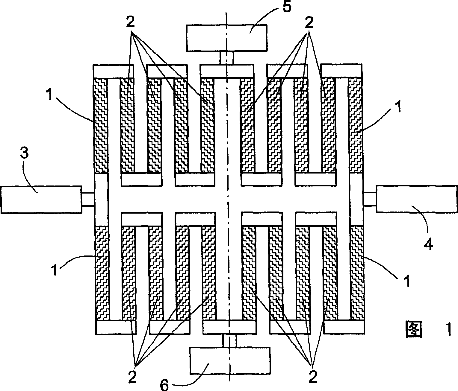
[0038] FIG. 1 shows the schematic structure of a known type of magnetoresistive sensor viewed in the plane of its conductor structure. The sensor comprises an arrangement of a plurality of strip-shaped conductors 1, 2 formed of magnetoresistive material and extending substantially parallel to each other in two rows, the boundary conductors of which are provided with reference numeral 1 forming the border of the conductor arrangement and are therefore described as peripheral strips, Whereas the other conductors provided with reference numeral 2 are bounded on all sides by at least a further conductor 1 or 2 which is considered to extend "inside" the conductor arrangement and is therefore referred to below as an inner conductor. The four adjacent conductors of the inner conductor 2 in each case and the peripheral strip 1 adjacent to it in each row of conductors are electrically connected to each other in the illustrated embodiment and represent the branches of a circuit formed as...


PUM


Abstract

The invention relates to a magnetoresistive sensor having at least one strip-shaped conductor that is formed from a magnetoresistive material and that is designed to determine its electrical resistance, which can be influenced by an external magnetic field, and/or to be acted on by an electric current. In order to construct a magnetoresistive sensor of this type in such a way that a further reduction in the hysteresis and an improved linearity are obtained, at least one screening strip is provided according to the invention that is disposed at least substantially parallel to and at a predetermined spacing from the conductor and is electrically separated from it.

Description

technical field [0001] The invention relates to a magnetoresistive sensor having at least one strip conductor formed from a magnetoresistive material and designed to determine an electrical resistance, which can be influenced by an external magnetic field and / or acted upon by an electric current. Background technique [0002] Such sensors are preferably used for magnetic field, current, position and movement measurements. A particular field of application in this regard is, for example, the angular and rotational speed measurement of camshafts and crankshafts for various control systems in internal combustion engines. [0003] WO 98 / 57188 ​​A1 discloses a sensor comprising a substrate on which a plurality of resistive elements are arranged in a Wheatstone bridge circuit, at least one resistive element exhibiting a magnetoresistive effect. The resistance element is arranged in a branch forming the following connection: (a) the current input terminal is connected to the first...

Claims


Application Information

Patent Timeline
Patent Type & Authority Applications(China)
IPC IPC(8): G01R33/09H01L43/08
CPCG01R33/093B82Y25/00G01R33/09G01R33/096
Inventor M·德舍尔
Owner NXP BV
Why Eureka
Try Eureka