
Device for rotary working into coil or piece material

A technology of rotary processing and sheet materials, which is applied in the direction of shearing devices, metal processing, metal processing equipment, etc., can solve the problem of not being able to replace brackets, etc., to avoid waste, reduce manufacturing costs, and reduce preparation time. Effect

Inactive Publication Date: 2003-08-06
BOBST SA
View PDF3 Cites 8 Cited by
  • Summary
  • Abstract
  • Description
  • Claims
  • Application Information

AI Technical Summary

Problems solved by technology

Then, until now, the processing machines for the production of packages could not take advantage of imported important parts from other manufacturers, for example, could not replace their own machines with better rotary cut bracket parts (brackets) made by another manufacturer Bracket (bracket) in

Method used


Image

  • Device for rotary working into coil or piece material
  • Device for rotary working into coil or piece material
  • Device for rotary working into coil or piece material

Examples


Embodiment Construction

[0017] In order to clarify several terms commonly used in the following description to describe the orientation and position of certain components, it must be noted that the terms "machine direction" and "transverse direction" refer to the direction in which the roll or sheet material travels in the machine , while the terms "upstream" and "downstream" refer to the side closest to the machine inlet and machine outlet, respectively.

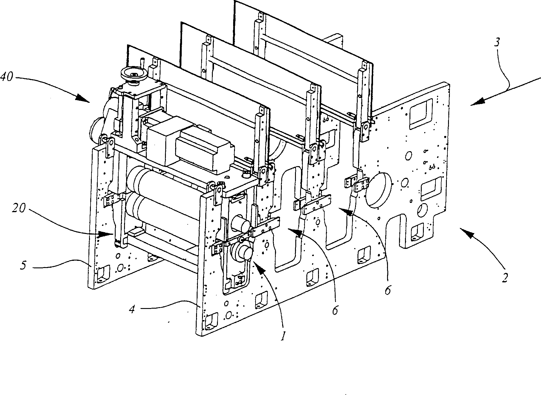
[0018] figure 1 is a perspective view showing the device 1 according to the invention in a conventional machine 2 for processing roll material. The running direction of the material (not shown in the figure) is from upstream to downstream as shown by arrow 3 in the figure. The frame of the machine 2 consists of two side walls 4,5. There is a wide oval or rectangular vertical opening 6 on the side wall, and devices for embossing (forming concave-convex patterns), forming creases, and cutting are respectively housed therein. exist figure 1 , onl...


PUM


Abstract

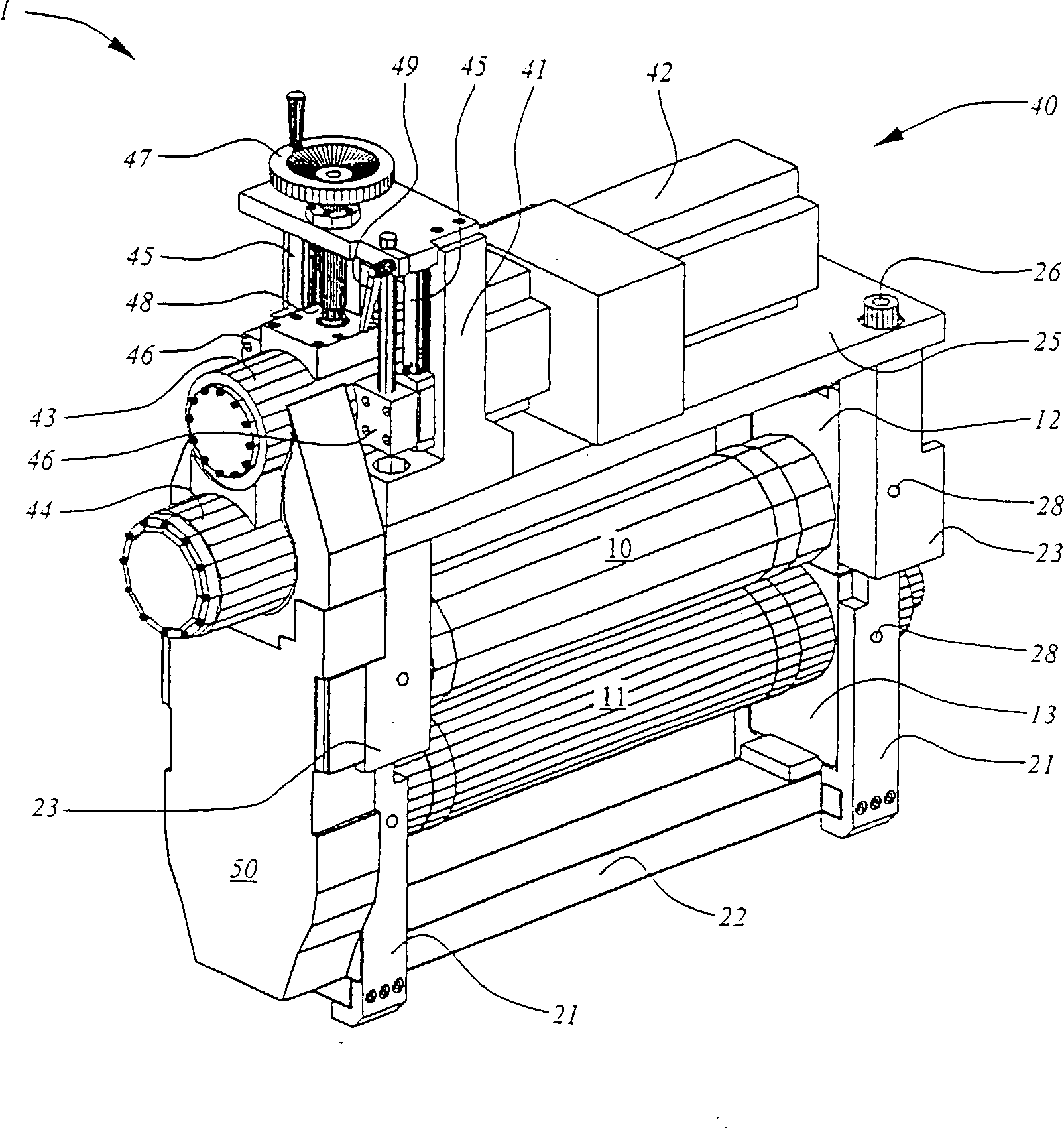
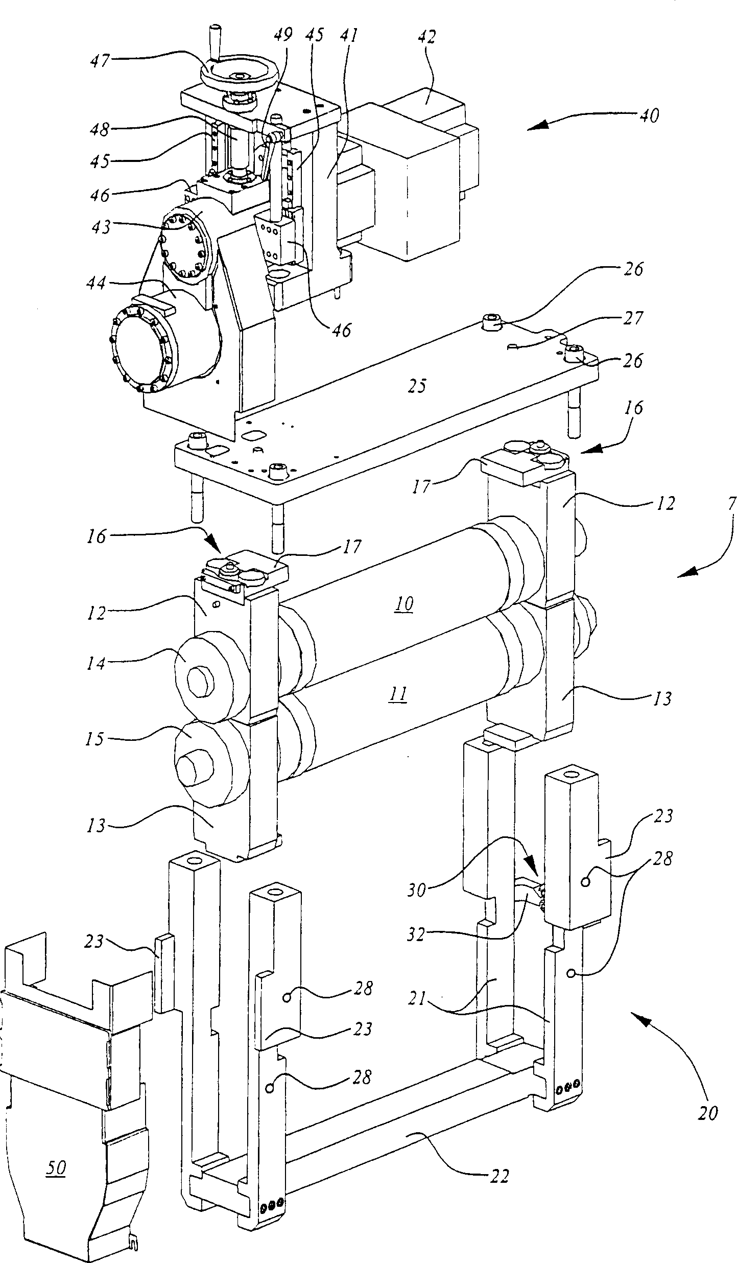
The device for rotary converting a web or sheet matter equips a processing station arranged in a machine (2) particularly producing packagings by means of cylindrical tools (10, 11). These tools are arranged in a cassette (7) and rotated by a driving device (40) equipped with a motor (42). The cassette (7), coming from an extrinsic equipment to that which normally equips the machine (2), is placed in another so-called adaptive cassette (20), which is removable and secured to the driving device (40). The latter is arranged on the adaptive cassette (20).

Description

field of invention [0001] The invention relates to a device for the rotary processing of roll or sheet material in the packaging industry's main machines for the manufacture of paper, cardboard or plastic folding box, box blanks. Background of the invention [0002] For example, converting rolls of cardboard into folding boxes, box blanks includes printing on the cardboard, embossing where the pattern will be embossed, making creases where needed, cutting and cutting. While peeling off the waste generated due to cutting. All these operations are performed at successive processing stations. These stations are driven synchronously to form the machinery for manufacturing packaging. [0003] The present invention is mainly used for the operations of above-mentioned embossing processing concave-convex patterns, forming creases and cutting processing. Each machining operation uses corresponding rotary tools which successively perform the aforementioned machining operations on t...

Claims


Application Information

Patent Timeline
Patent Type & Authority Applications(China)
IPC IPC(8): B23D35/00B26D1/40B26D7/26B31B1/00B31B1/14B31B50/25B31B50/56B31B50/88
CPCB23D35/008B26D7/2614
Inventor 马尔科·奇波利
Owner BOBST SA
Learn More