Device and method for displaying map

A map display device and map technology, which is applied to measurement devices, processing of 3D images, maps/plans/charts, etc., can solve the problems of difficult target recognition, difficulty in obtaining real map representation, and lack of recognition ability.

Inactive Publication Date: 2003-10-01
PANASONIC CORP
View PDF0 Cites 7 Cited by
  • Summary
  • Abstract
  • Description
  • Claims
  • Application Information

AI Technical Summary

Problems solved by technology

If any other objects to be displayed appear on the side of the road extending along the depth direction, the width of the widened road will appear to overlap with other displayed objects, which may make all objects difficult to identify
On the other hand, increasing the viewing point of the screen itself limits the viewing point, making it difficult to obtain a true map representation similar to that observed by the user's point of view.
Therefore, there is no effective conventional way to improve the recognition ability of these displayed objects which are degraded when they are displayed in 3D images

Method used


Image

  • Device and method for displaying map
  • Device and method for displaying map
  • Device and method for displaying map

Examples


no. 1 example

[0083] A first embodiment of the invention is now discussed. In the first embodiment, it is estimated whether a display object such as a road is oriented in the screen landscape. For any display object determined to be displayed in landscape orientation, the actual display mode of the display object is changed to increase the width of the display object. As a result, the navigation device according to the first embodiment improves the visual recognition performance of roads extending in the lateral direction.

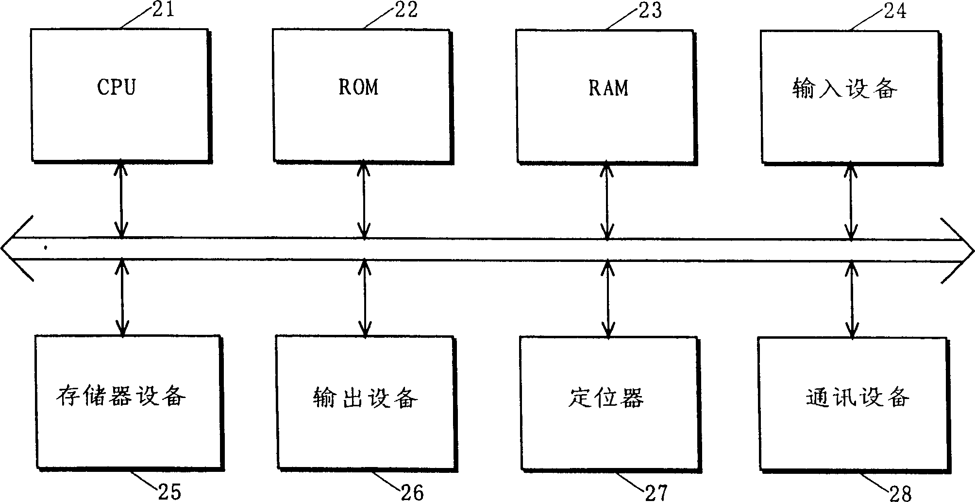
[0084] figure 2 is a schematic diagram of the hardware structure of the navigation device according to the first embodiment of the present invention. The navigation device according to the present embodiment, which is used for an automatic vehicle, includes a CPU 21 , a ROM 22 , a RAM 23 , a memory device 24 , an input device 25 , an output device 26 , a locator 27 , and a communication device 28 .

[0085] The ROM 22 is a programmable memory which previously stores...

no. 2 example

[0137] Discussing next the second embodiment of the present invention, in the first embodiment, due to the modification of the default display mode, a display object may conflict with another display object. Figure 14 This is an example of an image displayed when a display object conflicts with another display object. exist Figure 14 In , the roads 81 and 82 are deformed so that the width of the roads can be increased, so that the roads 81 and 82 overlap with the green area 84 . Thus, in the first embodiment, in which deformation processing is performed independently of any other display object display state, it is possible as Figure 14 Shown causes two or more display targets to conflict with another display target. A further improvement over the first embodiment is provided in the second embodiment.

[0138] Next, a navigation device according to a second embodiment is discussed. Figure 15 is a flowchart illustrating the flow of operation of the CPU 21 according to t...

no. 3 example

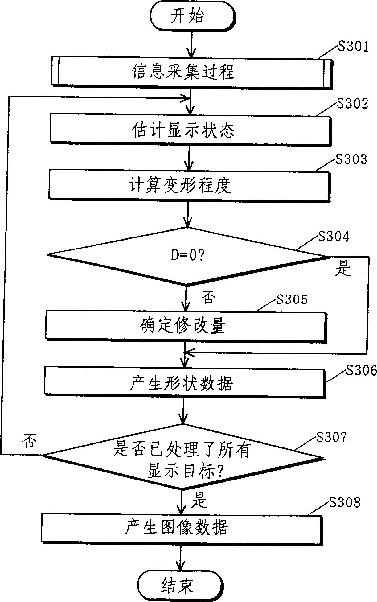
[0147] Next, a third embodiment of the present invention is discussed. According to the method of modifying the display mode of the third embodiment, the object representing the route (hereinafter referred to as "route object") can be modified so that it can appear "upright" in the 3D display image, unlike the first and second embodiments example. The navigation device according to the third embodiment has a figure 2 The structure of the navigation device of the first embodiment is shown. The operation according to the third embodiment is similar to the operation according to the first embodiment, except that image 3 Steps S302, S303, and S305 in. Therefore, the relevant steps S302 to S305 are specifically discussed below. In the third embodiment, it is assumed that only display objects that can be deformed are displayed for convenience of discussion of route objects.

[0148] According to the third embodiment, in image 3 The CPU 21 in the display state estimation pro...


PUM


Abstract

A device for displaying a map is provided which improves the visual recognition of objects displayed in a 3D image. The map data collection section 11 collects displayed map data for navigation purposes. The display state estimating section 12 receives the map data collected by the map data collecting section 11, and estimates the display state of the display object based on the map data. Display mode determining section 13 determines whether the display state estimated by display state estimating section 12 satisfies a predetermined condition, thereby determining whether the default display mode is to be modified. When it is determined that the modification is to be performed, the display mode determination section 13 modifies the default display mode to determine the actual display mode. Based on the display mode of each display object determined by display mode determination section 13 , display image generation section 14 generates image data for displaying a 3D map from the map data collected by map data collection section 11 .

Description

technical field [0001] The present invention relates to a map display device, and more particularly, to a three-dimensional map display device capable of displaying roads on a three-dimensional map. Background technique [0002] There is a type of map display device (for example, a navigation device) that allows two-dimensional (2D) map data to be viewed from different viewpoints, or it can be viewed in a three-dimensional manner based on three-dimensional (3D) map data previously constructed in a polygonal manner to display the map. Hereinafter, such devices are referred to as "3D map display devices". The 3D map display device enables users to have an intuitive understanding of the map. Figure 21 It is a schematic diagram illustrating an image displayed by a conventional 3D map display device. as Figure 21 As shown, the 3D map display device can provide a representation of real images. [0003] Some 3D map display devices have the function of searching for the best ro...

Claims


Application Information

Patent Timeline
Patent Type & Authority Applications(China)
IPC IPC(8): G09B29/00G01C21/00G01C21/32G06C21/00G06T17/05G08G1/0969G09B29/10
CPCG06T15/00G06T17/05G08G1/096827G08G1/096844G08G1/096861G09B29/106G01C21/3638
Inventor 山下敦士阪本清美濱田浩行濱田裕司高橋惠一
Owner PANASONIC CORP
Why Eureka
Try Eureka