
Feedforward DC bias canceller for direct conversion receiver

A technology of DC bias and receiver, applied in the direction of analog-to-digital converter, code conversion, analog-to-digital conversion, etc., which can solve the problems of high complexity, low calculation efficiency, and low efficiency of DC bias tracking method

Inactive Publication Date: 2003-10-01
NEC CORP
View PDF1 Cites 16 Cited by
  • Summary
  • Abstract
  • Description
  • Claims
  • Application Information

AI Technical Summary

Problems solved by technology

[0013] Different methods have been proposed for estimating the DC offset, but these methods almost all share some disadvantages, such as (1) slow response due to their feedback structure, (2) due to the offset noise passing through the entire analog baseband section during the detection time , causing ADC and baseband amplifier saturation, (3) ADCs requiring high resolution, (4) high complexity and computationally inefficient, (5) DC bias tracking method inefficient

Method used


Image

  • Feedforward DC bias canceller for direct conversion receiver
  • Feedforward DC bias canceller for direct conversion receiver
  • Feedforward DC bias canceller for direct conversion receiver

Examples


Embodiment Construction

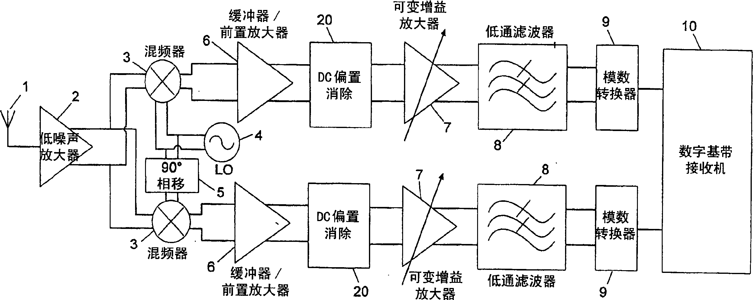
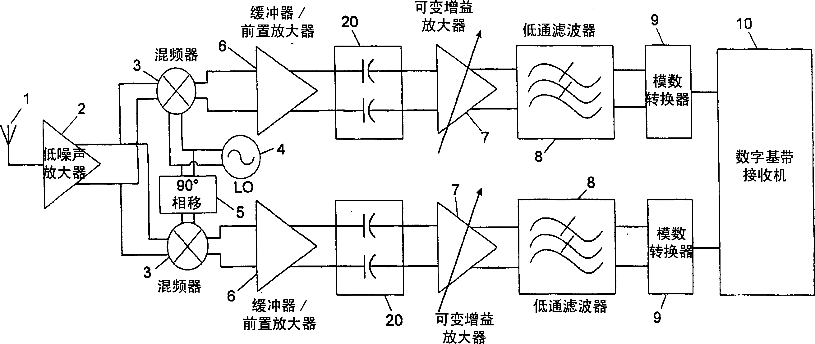
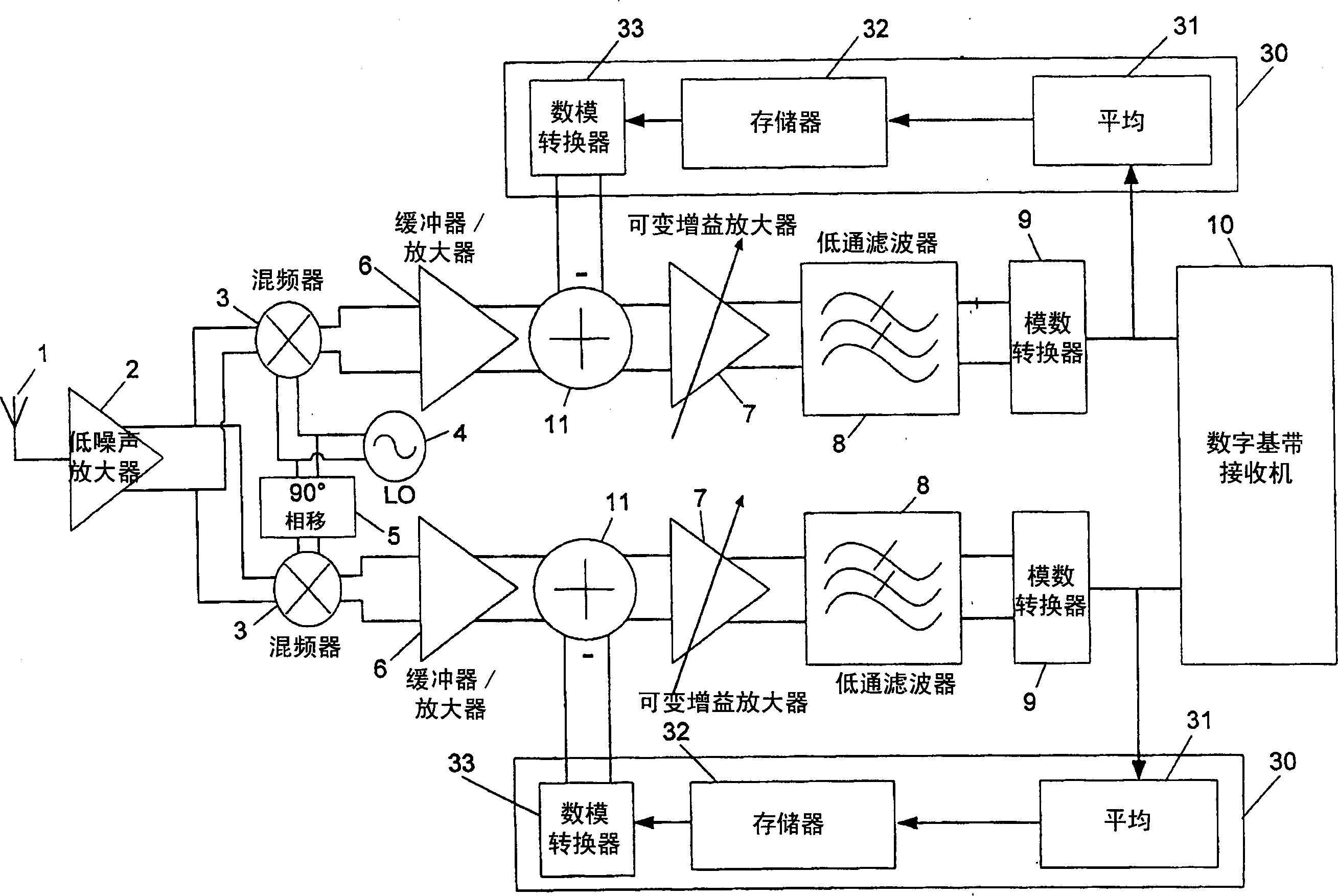
[0068] Fig. 3 shows a block diagram of a DCR using the feed-forward DC offset canceller of the first embodiment. The down-converted signal, which carries a weak signal corrupted by a strong DC bias, goes through a feed-forward structure and is corrected before entering the analog baseband section.

[0069] The feed-forward DC offset canceller includes an analog-to-digital converter 42 , a DC offset estimation and tracking section 44 , and a digital-to-analog converter (DAC) 46 . The downconverted signal is monitored by a low resolution ADC 42 and the signal samples are fed to a DC offset estimation and tracking section 44 . DC offset estimation and tracking is at the heart of offset cancellation methods, and it is important to use simple and uncomplicated methods to accomplish this task quickly and efficiently. After estimation, the DC offset is converted to an analog signal and subtracted from the downconverted signal at the input of the analog baseband section.

[0070] Di...


PUM


Abstract

A feed-forward DC offset canceller for use in wireless systems with direct conversion receiver (DCR) architectures, where the DC offset is estimated from the down-converted signal at the output of the mixer and applied before the signal is applied to the analog baseband section Eliminate bias. A linear digital filter estimates and tracks the DC offset, which is subtracted from the downconverted signal before simulating the baseband input. According to different environments and standard requirements, the response of the filter can be adjusted through its coefficients. Although higher order filters can be used as required, a first order recursive filter is preferred because of its simple and effective structure.

Description

technical field [0001] The present invention relates to a feedforward biasing structure (compared to a feedback structure) for canceling the DC offset of a downconverted RF signal in a direct conversion receiver (DCR). Background technique [0002] To illustrate the background and / or state of the art of the present invention, the following four references are generally referred to together: B. Razavi, "Design Consideration for Direct-Conversion Receivers" ("Design Considerations for Direct-Conversion Receivers"), IEEE Transactins on Circuits and Systems, Vol.44.No.6, June1997 ("Reference 1" in this article); W. Namgoong, "Direct-Coversion RF Receiver Design" ("Direct Conversion RF Receiver Design"), IEEE Transactions on Communications, Vol, 49, No.3, March 2001 (herein referred to as "Reference 2"); A. Abidi, "Direct-Conversion RadioTransceivers for Digital Communications" ("Direct Conversion Radio Transceivers for Digital Communications"), IEEE Journal of Solid-State Circu...

Claims


Application Information

Patent Timeline
IPC IPC(8): H04L27/00H03M1/06H03M1/12H04B1/10H04B1/16H04B1/26H04B1/30H04L27/22
CPCH03M1/0607H03M1/0626H03M1/12H04B1/30
Inventor 巴巴克·索尔塔尼安穆罕默德·马迪希恩
Owner NEC CORP
Learn More