Rolling bearing esp. for dynamo

A technology of bearing device and bearing raceway, which is applied in the field of motors, and can solve the problems of reducing the life of the bearing frame

Inactive Publication Date: 2003-10-08
AB SKF
View PDF1 Cites 17 Cited by
  • Summary
  • Abstract
  • Description
  • Claims
  • Application Information

AI Technical Summary

Problems solved by technology

The abnormal axial loads mentioned above are likely to detrimentally reduce the life of the bearing frame

Method used


Image

  • Rolling bearing esp. for dynamo
  • Rolling bearing esp. for dynamo
  • Rolling bearing esp. for dynamo

Examples


Embodiment Construction

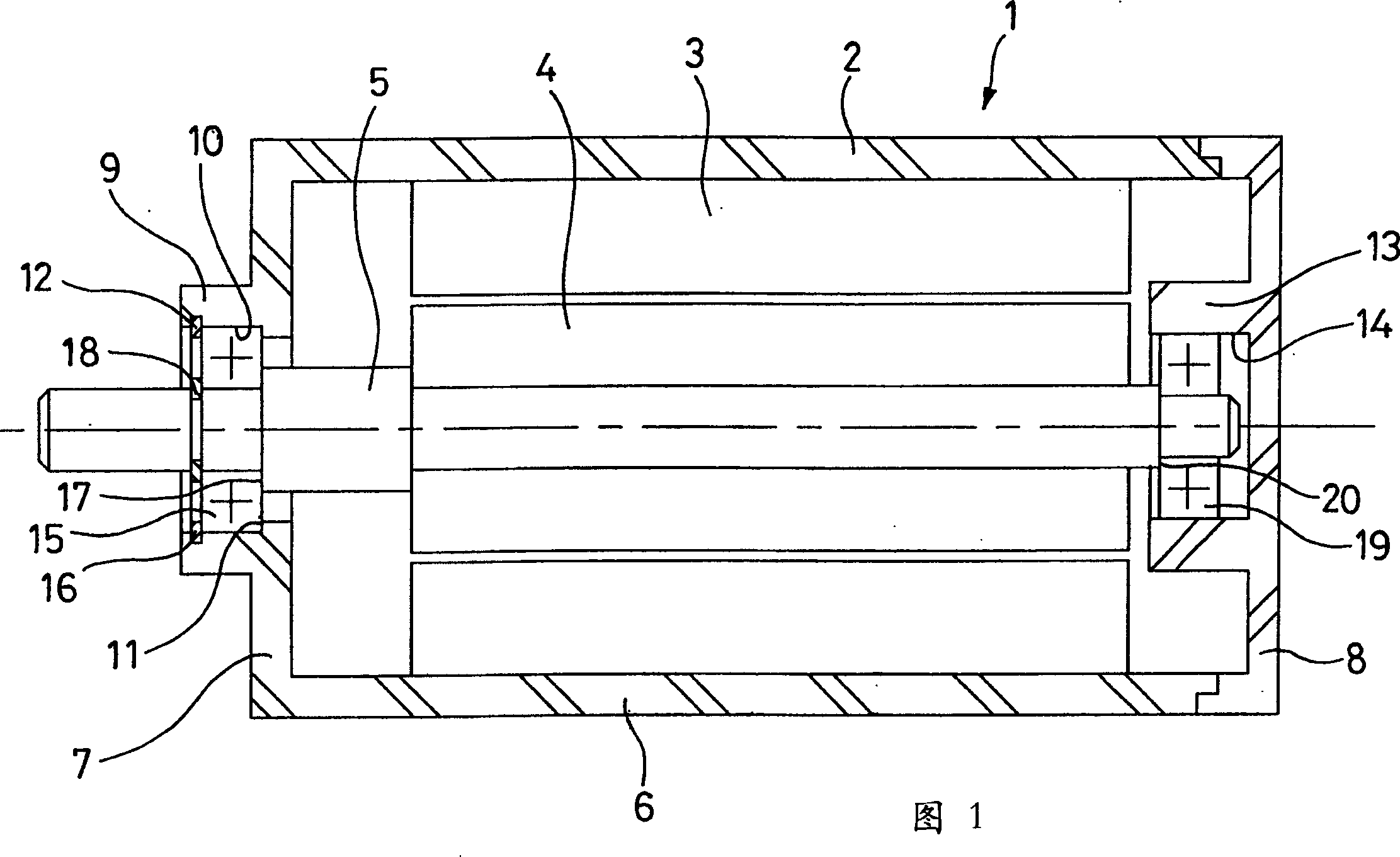
[0040] It can be seen from Fig. 1 that the motor 1 includes a housing 2 made of light alloy, a stator 3 integrated with the housing 2, a rotor 4 and a shaft 5 on which the rotor 4 is mounted. The housing 2 includes a substantially cylindrical part 6, a radial ring part 7 positioned at one end of the cylindrical part 6, and a radial part 8 positioned at the opposite end and having an annular shape.

[0041] The axial part 9 with the cylindrical bore 10, the shoulder 11 adjacent to the bore 10 and the groove 12 arranged along the bore 10 relative to the shoulder 11 are integrated with the radial annular part 7. The axial portion 13 with the cylindrical bore 14 is integrated with the radial annular portion 8 and extends axially toward the inside of the motor 1. A conventional type of bearing 15 is installed in the bore 10 of the axial flange 9 through its outer ring, and is axially fixed by a shoulder 11 and a circlip 16 provided in the groove 12. The bearing 15 is mounted on the out...


PUM


Abstract

A bearing assembly (21), comprises an outer race (24) adjusting in the cylindrical flute. The outer race (24) comprises a runner face in contact with several balls (26) etc., while at least one expansion compensating race (35) is located in an annular groove (33) in the cylindrical outer face of the outer race. The expansion compensating race is of material with a larger expansion coefficient than that of the outer race. The expansion compensating race has an outer diameter between the outer diameter of outer race, minus 50 microns, and the outer diameter of outer race, plus 20 microns.

Description

Technical field [0001] The present invention relates to the field of rolling bearings, especially used in motors such as motors. Background technique [0002] A motor generally includes a housing in which a stator and a rotor installed to rotate in the stator are fixed. The motor is mounted to rotate by means of two bearings, which are generally rigid ball bearings, which are positioned on each end of the rotor shaft. [0003] "Rigid ball" type bearings usually have a ring-shaped cross section of the bearing raceway, which is symmetrical with respect to the plane passing through the center of the ball, and the bearing acts on large radial loads and moderate axial loads. The two bearings are mounted on the shaft by means of their inner rings with a press fit. [0004] The outer ring of the bearing is installed in the cylindrical groove of the motor housing, which is generally made of light aluminum alloy. The outer ring of one of the two bearings is axially fixed in the motor hous...

Claims


Application Information

Patent Timeline
Patent Type & Authority Applications(China)
IPC IPC(8): F16C25/08F16C19/52F16C35/077H02K5/16H02K5/173H02K5/24
CPCF16C19/06F16C19/52F16C19/525H02K5/1732F16C35/077F16C33/586F16C2202/22F16C2380/26
Inventor 米歇尔·鲍特鲁克斯阿米尔·L·多耶尔弗朗西斯科·加卢奇
Owner AB SKF
Why Eureka
Try Eureka