
CD recording method of setting up optimal recording power for recording data and CD recording device

A technology for recording power and recording data, applied in the direction of optical recording/reproduction/erasing methods, data recording, optical recording heads, etc., can solve the problems of large difference in recording rate and difficulty in achieving high-quality recording

Inactive Publication Date: 2003-10-08
YAMAHA CORP
View PDF1 Cites 7 Cited by
  • Summary
  • Abstract
  • Description
  • Claims
  • Application Information

AI Technical Summary

Problems solved by technology

However, since this recording power function is obtained linearly by interpolation, the optimum recording power in the middle region at one recording speed will be the same as the interpolated power different
Therefore, it is difficult to achieve high-quality recording

Method used


Image

  • CD recording method of setting up optimal recording power for recording data and CD recording device
  • CD recording method of setting up optimal recording power for recording data and CD recording device
  • CD recording method of setting up optimal recording power for recording data and CD recording device

Examples


Embodiment Construction

[0050] The invention can be used to record data on write-once optical discs that can only record data once, such as CD-R, DVD-R, etc., and re-writable optical discs that can write data repeatedly, such as CD-RW, DVD-R, etc. In the case of RW, DVD+RW, DVD-RAM, etc., the following takes CD-R as an example.

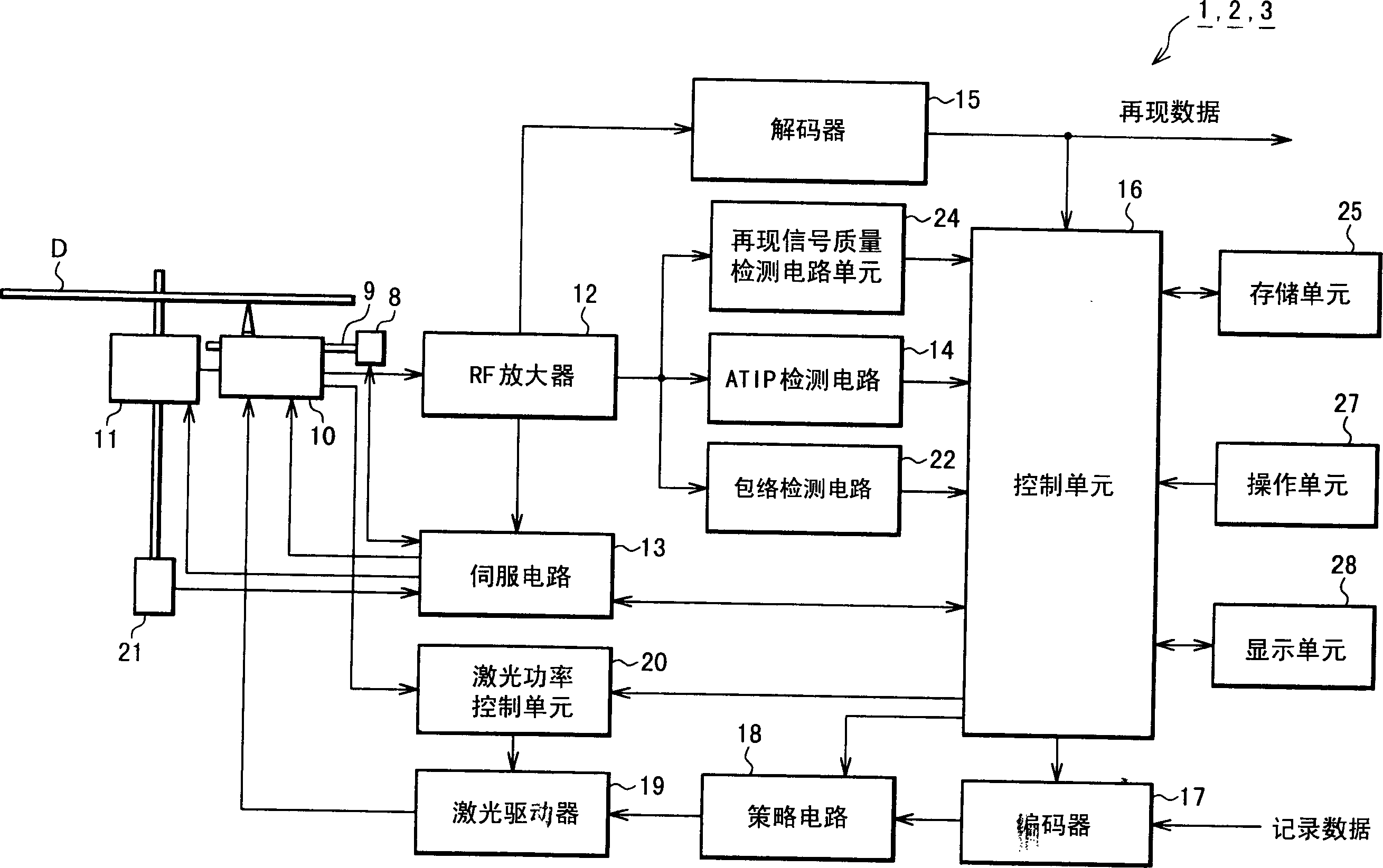
[0051] figure 1 This is the structure of an optical disc recording device according to an embodiment of the present invention. Such as figure 1 As shown, the optical disc recording apparatus 1 has a feed motor 8 and a guide rail 9 as a moving unit, an optical pickup 10, a spindle motor 11 as a rotating device, an RF amplifier 12, a servo circuit 13, an ATIP detection circuit 14, a decoder 15, Control unit 16, encoder 17, strategy circuit 18, laser driver 19, laser power control unit 20, frequency generator 21, envelope detection circuit 22, reproduction signal quality detection circuit unit 24, storage unit 25 , Operation unit 27h and display unit 28.

[0052] The feed motor ...


PUM

PropertyMeasurementUnit
diameteraaaaaaaaaa

Abstract

A method for recording an optical disc, comprising the steps of: setting a recording parameter function, which represents the relationship between a recording rate for recording data in an optical disc and a parameter for optimally controlling a recording power control waveform, the recording The power control waveform is used to control the recording power of the light beam irradiated on the optical disc for recording data; before actual data recording is performed in the optical disc, by performing test recording in a test area of ​​the optical disc at a recording rate or multiple recording rates, obtain The optimum value of the parameter; correcting the recording parameter function according to the obtained optimum value of the parameter; using the corrected recording parameter function to obtain the parameter corresponding to the recording rate; recording data by irradiating a light beam of the recording power control waveform , the recording power control waveform is applied with the acquired parameters.

Description

[0001] This application is based on the Japanese Patent 2002-080962 filed on March 22, 2002, and the entire contents are cited. Technical field [0002] The present invention relates to a technique for recording data by setting an optimal recording power even when there is a large difference in the recording rate between a write-once optical disc and a rewritable optical disc. Background technique [0003] In recent years, the rate of recording data in constant linear rate (CLV) recording discs (hereinafter referred to as optical discs) is similar to rewritable discs such as CD-R and DVD-R, and write-once such as CD-RW and DVD-RAM. Into the optical discs are moving in the direction of high speed. Adjust the disc by fixing the recording density to record data. Therefore, the existing optical discs record data at a fixed transmission rate through the constant linear rate method (CLV). However, with the advancement of technology, recording methods with higher recording rates have beg...

Claims


Application Information

Patent Timeline
Patent Type & Authority Applications(China)
IPC IPC(8): G11B7/0045G11B7/006G11B7/007G11B7/125G11B7/1263G11B7/1267
CPCG11B7/00456G11B7/0062G11B7/0079G11B7/1263G11B7/1267
Inventor 松本圭史
Owner YAMAHA CORP
Learn More