Synchronous induction motor

A technology for induction motors and rotors, applied to electric components, capacitors, electromechanical devices, etc., can solve problems such as rotor wear and achieve the effect of preventing wear and magnetization

Inactive Publication Date: 2003-10-08
SANYO ELECTRIC CO LTD
View PDF0 Cites 23 Cited by
  • Summary
  • Abstract
  • Description
  • Claims
  • Application Information

AI Technical Summary

Problems solved by technology

Therefore, the rotor will still have the problem of wear

Method used


Image

  • Synchronous induction motor
  • Synchronous induction motor
  • Synchronous induction motor

Examples


Embodiment Construction

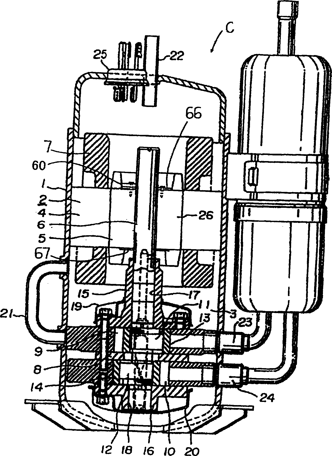
[0059] Next, embodiments of the present invention will be described in detail based on the drawings. figure 1 It is an illustration of a vertical side view of a hermetic electric compressor C to which the synchronous induction motor 2 of the present invention is applied. In the figure, 1 is an airtight container, the synchronous induction motor 2 is accommodated in the upper side inside, and the compressor 3 rotationally driven by the synchronous induction motor 2 is accommodated in the lower side. The airtight container 1 accommodates the synchronous induction motor 2 and the compressor 3 divided into two in advance, and then seals it by high-frequency welding or the like. Also, the hermetic electric compressor C may be, for example, a rotary, reciprocating, or scroll compressor.

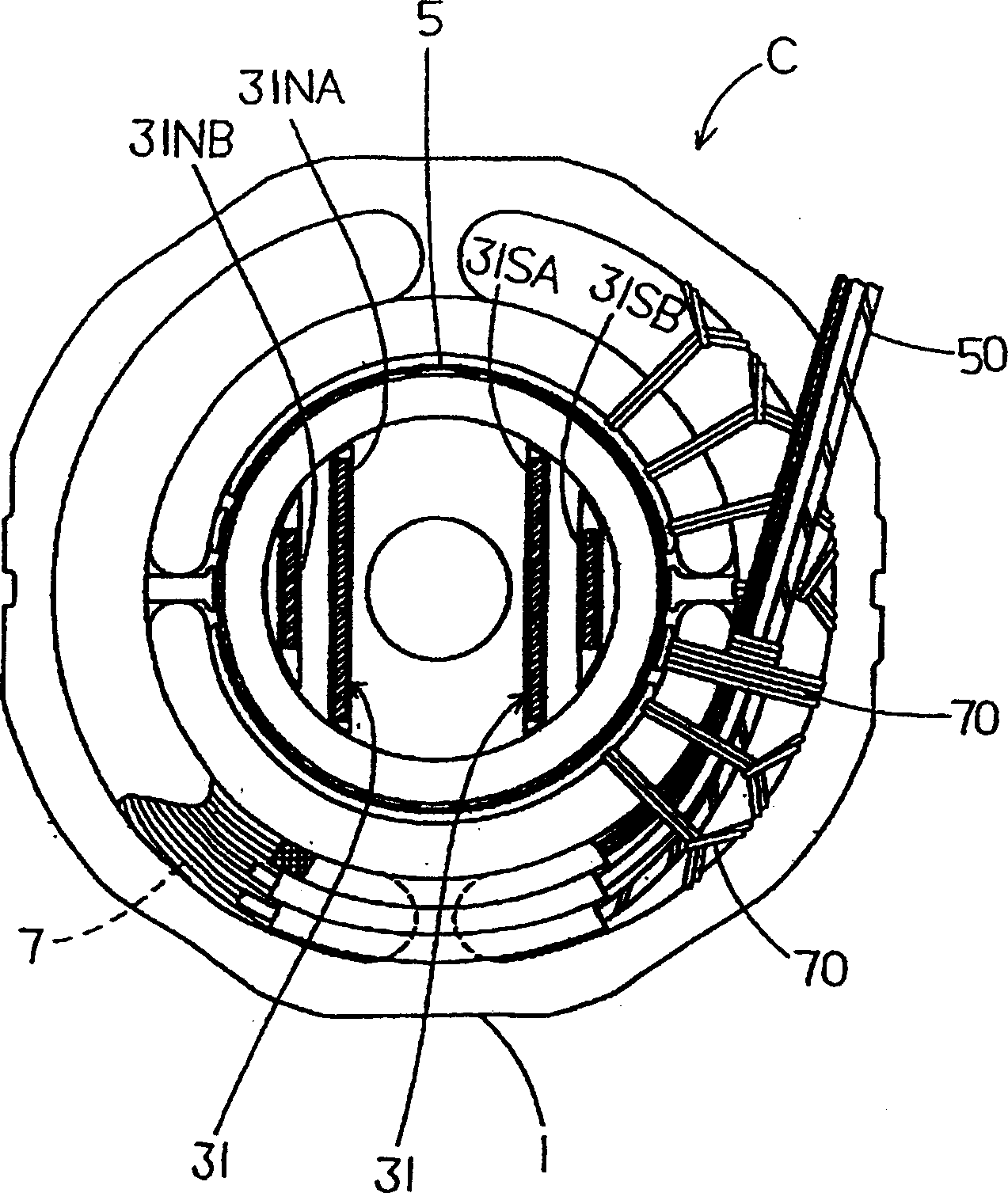
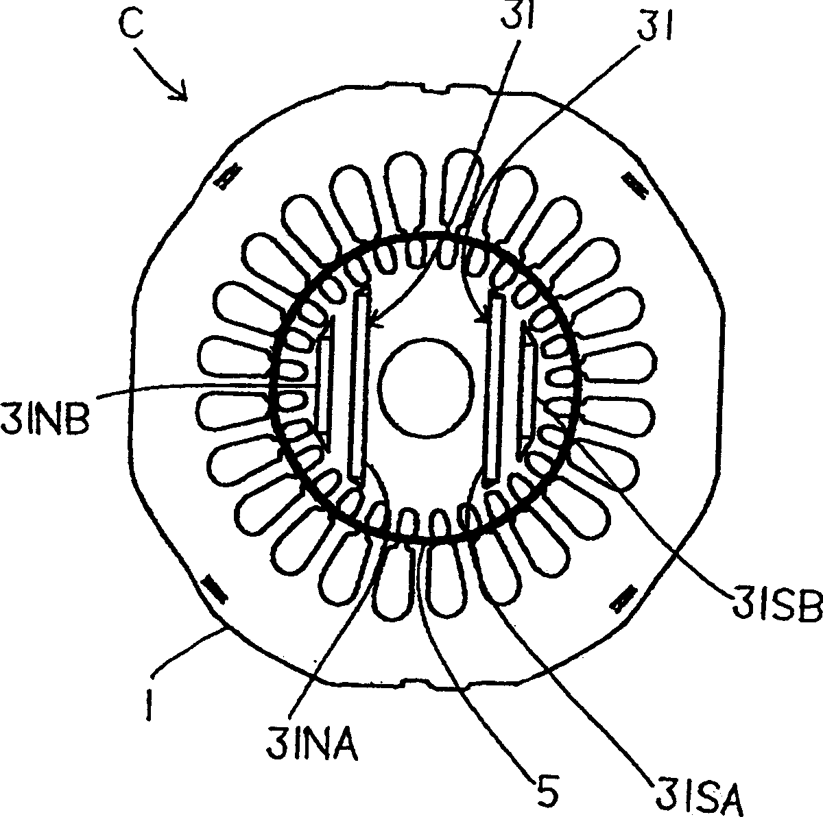
[0060] The synchronous induction motor 2 has a single-phase two-pole structure, and is composed of a stator 4 fixed to the inner wall of the airtight container 1 , and a rotor 5 rotatably supporte...


PUM


Abstract

A synchronous induction motor 2 comprises a stator 4 which has a stator winding 7, and the rotor 5 which is fixed to the rotary shaft 6, and rotates inside the stator 4. A secondary conductor disposed in the peripheral part of a rotor yoke part which constitutes the rotor 5, and permanent magnets, embedded in the rotor yoke part, are provided. The permanent magnets are disposed on both sides interposing the rotary shaft 6. The permanent magnets which pull in magnetic field constituted by the permanent magnets are disposed on both sides of a line which passes through the permanent magnets and the rotary shaft 6. Providing a synchronous induction motor, which largely prevents magnetization of a rotary shaft to which a rotor of the synchronous induction moor comprising two poles is fixed.

Description

technical field [0001] The present invention relates to a synchronous induction motor including a secondary conductor provided on a peripheral portion of a rotor contact portion and a permanent magnet embedded in the rotor contact portion. Background technique [0002] In known art examples, induction motors or DC brushless (DC brushless) motors driven by commercial power sources have been used as motors for driving hermetic electric compressors constituting the refrigeration cycle of air conditioners or refrigerators. These electric motors are fixed to an airtight container, and include a stator having a stator coil and a rotor rotating within the stator. In the induction motor system, the rotor is rotated by supplying a commercial power supply to the stator winding. [0003] Furthermore, the electric motors used in recent years have a two-pole structure in which permanent magnets are embedded in the rotor of the induction motor. The synchronous induction motor with a sin...

Claims


Application Information

Patent Timeline
Patent Type & Authority Applications(China)
IPC IPC(8): H02K1/00H02K1/27
CPCY02B30/741H01G2/10H05K9/0081
Inventor 簗岛俊人小礒繁美五十岚惠司郎榎本和广竹泽正昭中山善友新井和彦村田荣一小野寺昇
Owner SANYO ELECTRIC CO LTD
Why Eureka
Try Eureka