High power lighting system and fluorescent lamp

A lighting system, fluorescent lamp technology, applied in the field of fluorescent lamps, can solve the problems of electronic current reduction, poor cooling effect, electrode filament consumption, etc.

Inactive Publication Date: 2003-10-15
PANASONIC CORP
View PDF0 Cites 0 Cited by
  • Summary
  • Abstract
  • Description
  • Claims
  • Application Information

AI Technical Summary

Problems solved by technology

Therefore, the electrode filament is consumed more rapidly
In addition, when reducing the lamp current to dim, this also means that the electron current is reduced
As a result, fewer electrons are emitted from the surface of the electrode filament, thus resulting in poorer cooling

Method used


Image

  • High power lighting system and fluorescent lamp
  • High power lighting system and fluorescent lamp
  • High power lighting system and fluorescent lamp

Examples


Embodiment Construction

[0030] Hereinafter, an embodiment in which the lighting system of the present invention is applied to a down lighting device will be described with reference to the drawings.

[0031] I. Structure of downward lighting device

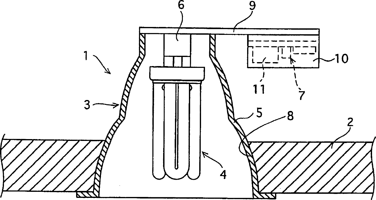
[0032] Fig. 1 is a view showing the overall construction of the downlighting device of the present invention, in which a part of the drawing is cut away to show the internal structure. As shown in the figure, the down lighting device 1 includes a main body 3 embedded in a ceiling 2, and a compact single-cap fluorescent lamp 4 (hereinafter simply referred to as "fluorescent lamp 4") connected to the main body 3.

[0033] (1) Subject

[0034] The main body 3 is provided with a shading assembly 5 expanding downwards, a socket assembly 6 disposed within the shading assembly 5 for detachably connecting the fluorescent lamp 4 thereto, and a fluorescent lamp operatively connected to the socket assembly 6 at maximum brightness level and dimming level 4 electro...


PUM


Abstract

A lighting system includes a fluorescent lamp 4 and a main body 1 for attaching the fluorescent lamp 4 thereto. The main body 1 is provided with a socket assembly 6 for the attachment of the fluorescent lamp 4, and an electronic ballast 7 for operating the fluorescent lamp 4 at dimmed levels (as well as at the full light level). The fluorescent lamp 4 is composed of a discharge tube formed of four U-shaped glass tubes that are connected together to form a square in plan view. Each glass tube has an inner diameter of 13.5 mm, and the discharge tube is filled with a rare gas containing neon and argon (at 50:50 ratio by volume). When operating the fluorescent lamp 4 at the full light level, the electronic ballast 7 applies the nominal lamp current of 0.43 A.

Description

technical field [0001] The present invention relates to a lighting system employing dimming control to operate a fluorescent lamp, and to a fluorescent lamp. Background technique [0002] A compact single-base fluorescent lamp (hereinafter referred to as "fluorescent lamp") is becoming popular due to its high lamp efficiency as a lamp unit installed in commercial places and offices in a manner embedded in the ceiling (hereinafter, this The lamp unit is referred to as a "downlighting unit"). [0003] There are many types of fluorescent lamps, with different lamp powers for different applications and purposes. In this fluorescent lamp, the outer diameter of the glass tube constituting the discharge tube is uniform, and the rated lamp current is uniform. However, due to the different lengths of the discharge tube and the different ratios of the neon and argon contents sealed in the discharge tube, the lamp power of each fluorescent lamp is different. [0004] For example, wh...

Claims


Application Information

Patent Timeline
Patent Type & Authority Applications(China)
IPC IPC(8): H01J61/16H01J61/32H01J61/72H05B41/298
CPCH05B41/2988
Inventor 明星稔北田昭雄清水直
Owner PANASONIC CORP
Why Eureka
Try Eureka