
Halogen lamp

A halogen lamp and halogen technology, applied in the field of halogen lamps, can solve the problem of high cost and achieve the effect of avoiding the blackening of the lamp tube

Inactive Publication Date: 2015-01-28
KUNSHAN BOWEN LIGHTING TECH
View PDF5 Cites 0 Cited by
  • Summary
  • Abstract
  • Description
  • Claims
  • Application Information

AI Technical Summary

Problems solved by technology

The general and large amount of inert gas used in the lamp tube as a filling component is very expensive

Method used


Image

  • Halogen lamp

Examples


Embodiment Construction

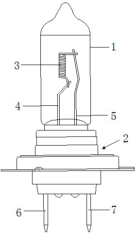
[0015] The drawing shows a schematic diagram of the structure of a halogen lamp according to a preferred exemplary embodiment. Such halogen lamps are so-called H8 lamps, which are intended to be operated in motor vehicles with a nominal voltage of 12 volts. The lamp has a maximum power consumption of only 43 watts at an operating voltage of 13.2 volts.

[0016] The halogen lamp according to the preferred exemplary embodiment has a substantially cylindrical glass bulb 1 which is provided with a base 2 at one end. An axially oriented spiral filament 3 is arranged inside the lamp tube 1 , and the filament outlet wrapped with a small molybdenum tube is welded with the current leads 4 and 5 respectively. The two current leads 4 , 5 are electrically conductively connected to the electrical connections 6 , 7 of the lampholder 2 respectively. The lamp tube 1 is made of quartz glass or hardened glass, for example aluminosilicate glass.

[0017] A filling with a halogen component and...


PUM


Abstract

The invention relates to a halogen lamp, and the halogen lamp comprises at least one tungsten filament (3) arranged in a diaphanous modulator tube and a filler in the modulator tube (1), wherein the filler comprises a halogen element applied for a halogen cycle and an inert gas element including krypton or xenon, the inert gas element includes at least one additional one, the radius of the atom is less than that of the krypton atom, and the cold filling pressure in the modulator tube (1) is more than or equal to 0.7 MPA. The halogen lamp is especially suitable for a light source used as a steering lamp or a daytime running light and a positioning light combined in a vehicle.

Description

technical field [0001] The invention relates to a halogen lamp according to the preamble of claim 1 . Background technique [0002] Such a halogen lamp is known, for example, from EP 0 370 318 A2. This document describes a halogen lamp for operation at high temperatures, which has a light-transmitting tube and a tungsten wire arranged in the tube and a filling inside the tube, wherein the filling consists of carbon , hydrogen, inert gases, phosphorus, chlorine and bromine mixture. The molar ratio of the combined total of chlorine and bromine to carbon is greater than 1, and the molar ratio of phosphorus to the combined total of chlorine and bromine is in the range of 0.5 to 2. As inert gases the gases nitrogen, xenon, krypton, argon or helium are proposed. In EP 1 255 279 A2 a small halogen lamp is described whose The fill has a cold fill pressure ranging from 0.5 MPa to 3 MPa and its inert gas composition includes xenon. The general and large amount of inert gas used as...

Claims


Application Information

Patent Timeline
Patent Type & Authority Applications(China)
IPC IPC(8): H01K1/50H01K1/56
CPCY02B20/00
Inventor 熊开富
Owner KUNSHAN BOWEN LIGHTING TECH
Learn More