Image forming device

An image and setting device technology, applied in the direction of electrical recording technology using charge graphics, image communication, equipment using electrical recording technology using charge graphics, etc., can solve the problem of ensuring the voltage stability of charge pump capacitor 15 The adjustment of the deceleration amount is difficult, the fluctuation of the rotation speed becomes large, and the adjustment of the motor drive unit 14 is difficult, etc., and the effect of small speed fluctuation, suppression of the fluctuation of the rotation speed, and low cost is achieved.

Inactive Publication Date: 2003-10-22
CANON KK
View PDF0 Cites 3 Cited by
  • Summary
  • Abstract
  • Description
  • Claims
  • Application Information

AI Technical Summary

Problems solved by technology

[0030] However, in the conventional polygon motor control circuit 111, the interval for detecting the rotation speed fluctuation of the polygon motor 104 becomes a long interval corresponding to six BD signals, so there is a possibility that the rotation speed fluctuation becomes large.
[0031] In addition, because the interval between generating the ACC signal and the DEC signal becomes longer, it is difficult to adjust the motor drive unit 14 for controlling the polygon motor 104 to rotate stably. Specifically, in the conventional polygon motor control circuit 111, There is a problem that it becomes difficult to ensure the voltage stability of the charge pump capacitor 15 and to adjust the acceleration / deceleration amount for one acceleration / deceleration instruction.

Method used


Image

  • Image forming device
  • Image forming device
  • Image forming device

Examples


Embodiment Construction

[0114] Hereinafter, embodiments of the present invention will be described in detail with reference to the drawings.

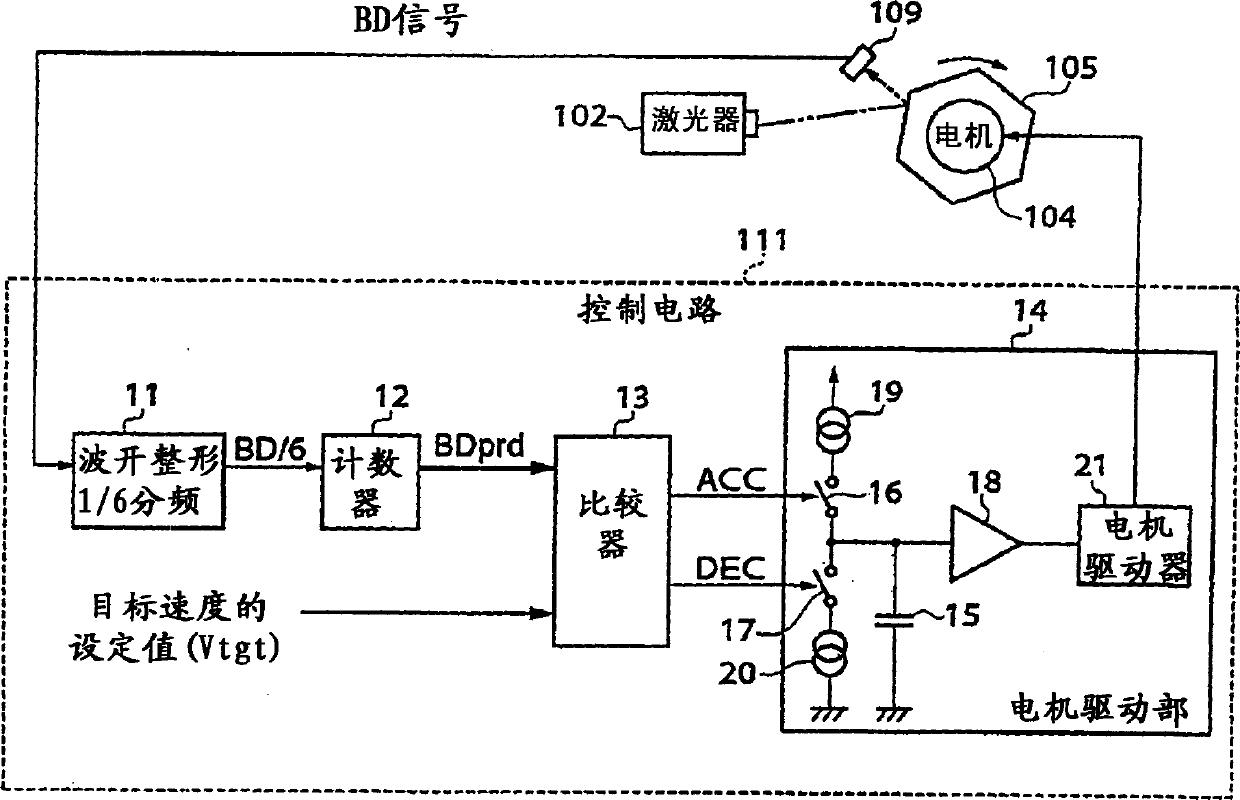
[0115] Fig. 7 is a block diagram of a polygon motor control circuit of the image forming apparatus according to Embodiment 1 of the present invention. The control circuit 111 as the polygon motor control circuit according to the first embodiment of the present invention performs various controls such as drive control of the polygon motor, and is mounted on an electrophotographic printer as an image forming apparatus.

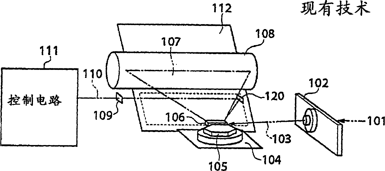
[0116] It should be noted that in FIG. 7 , the polygon motor to be controlled is schematically depicted, and the mirror 120 (see FIG. 1 ) for detecting the BD signal is omitted. In addition, since the configuration of the electrophotographic exposure scanning system is basically the same as that of the conventional polygon motor control circuit shown in FIG. 1, the same reference numerals are used for the same components, and their descriptions ...


PUM


Abstract

It is an object of the present invention to provide an image forming apparatus that is capable controlling the rotational speed of a polygon motor so as to reduce variations in the rotational speed of the polygon motor to the minimum possible level and enable steady rotation of the polygon motor with ease in controlling the rotational speed of the polygon motor to a target speed. When a photosensitive drum is exposure-scanned while the traveling direction of an exposure laser beam is deflected by the polygon mirror, a polygon motor for driving the polygon mirror is controlled according to target periods M or target speeds of the polygon motor, which are determined for respective mirror planes of the polygon mirror.

Description

technical field [0001] The present invention relates to an image forming apparatus that controls the speed of a motor (polygonal motor) that rotates and drives a rotating polygon mirror. Background technique [0002] Conventionally, in a laser beam printer or the like using an electrophotographic method, as a method of controlling the rotational speed of a motor (hereinafter referred to as a polygon motor) that rotates a rotating polygon mirror, it is known to control the rotational speed of the polygon motor so that the A system in which the period of the main scanning synchronous signal (hereinafter referred to as BD signal) generated by rotating the reflected light of the laser beam at the reference position (for example, the start position) of each mirror surface of the polygon mirror coincides with the target period. [0003] An exposure scanning system of an electrophotographic printer has the structure shown in FIG. 1 . In FIG. 1, a laser unit 102 turns on / off a lase...

Claims


Application Information

Patent Timeline
Patent Type & Authority Applications(China)
IPC IPC(8): G02B26/12H04N1/053H04N1/113H04N1/12
CPCH04N1/1135H04N2201/04755H04N1/053H04N2201/0471H04N1/12G02B26/122H04N2201/02439H04N2201/04794H04N2201/04793H04N2201/04744H04N2201/04732
Inventor 菅野觉
Owner CANON KK
Why Eureka
Try Eureka