Kitchen refuse treating device
A kitchen waste and processor technology, which is applied in the fields of temperature control sludge treatment, dewatering/drying/concentrating sludge treatment, lighting and heating equipment, etc., can solve problems such as unevenness and achieve the effect of suppressing odor
- Summary
- Abstract
- Description
- Claims
- Application Information
AI Technical Summary
Problems solved by technology
Method used
Image
Examples
Embodiment 1
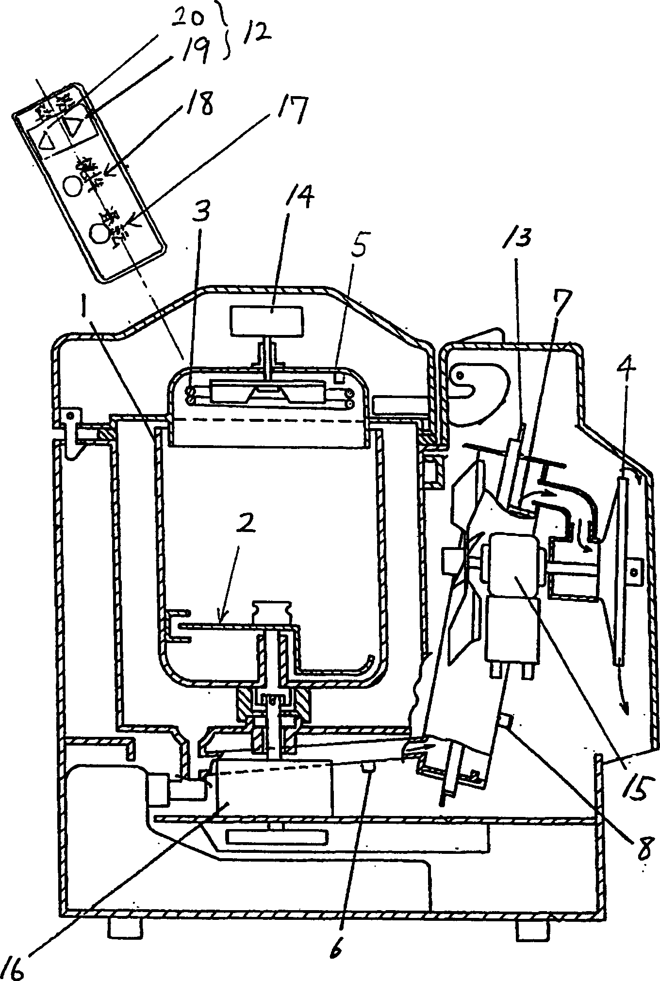
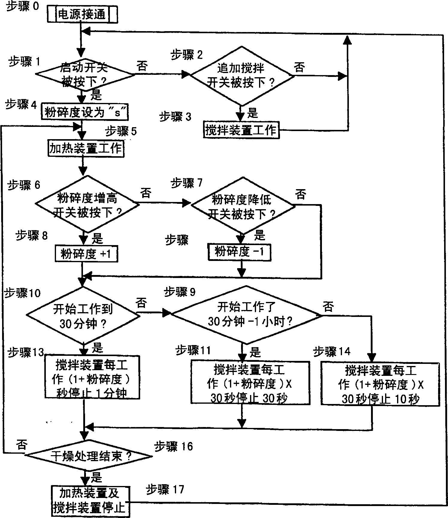
[0028] use below figure 1 , 2 A first embodiment of the present invention will be described. in, figure 1 It is an overall structural diagram of the kitchen waste disposer in this embodiment, figure 2 It is a flow chart showing the operation of the kitchen waste disposer.
[0029] Reference numeral 1 is a garbage storage container for inputting kitchen garbage to be processed, 2 is a stirring device for stirring the kitchen garbage put into the kitchen garbage storage container 1, and 3 is a mixing device for mixing the garbage into the garbage storage container 1. A drying heater is a heating device for heating the garbage put into the kitchen garbage storage container 1, 4 is an exhaust fan for exhausting the steam generated from the garbage being processed to the outside, and 5 is for detecting the kitchen garbage. The drying sensor of the internal temperature of the storage container 1, 6 is a stop detection sensor for grasping the temperature change and detecting t...
Embodiment 2
[0038] Use below image 3 , 4 A second embodiment of the present invention will be described. Here, for the same components as those in the above-mentioned first embodiment, we attach the same symbols, and the description thereof is omitted.
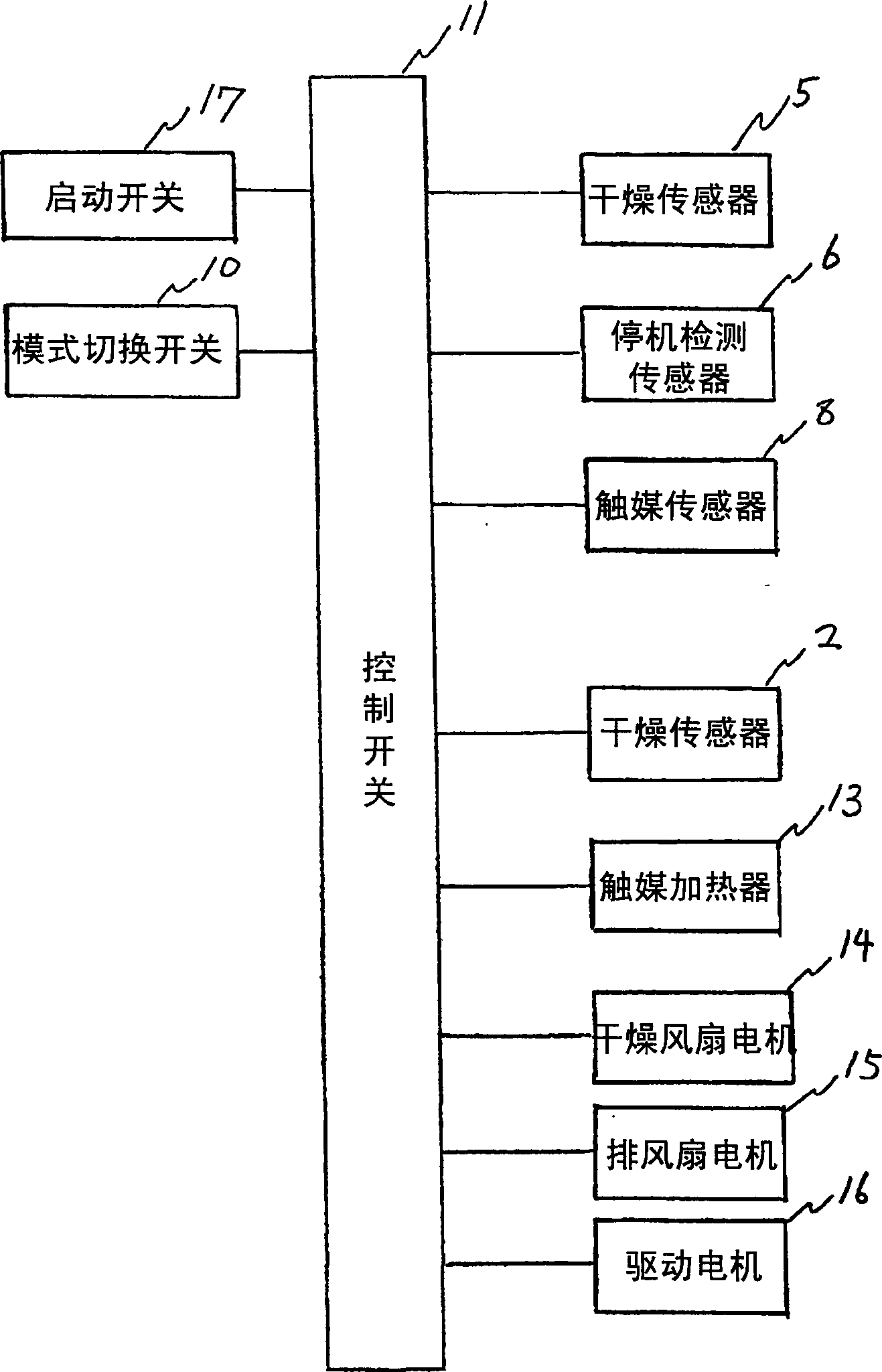
[0039] image 3 The circuit structure diagram of the kitchen garbage disposer of the present invention, Figure 4 A schematic diagram of its operation sequence.
[0040] The operation of the above structure will be described below. First, the user pours the kitchen garbage generated in the household into the garbage storage container 1, and presses the start switch 17 to start processing. Once the start switch 17 is pressed, the control device 11 will be driven, and each sensor such as the drying sensor 5, the shutdown detection sensor 6, the catalyst sensor 8, and the drying heater 3, the catalyst heater 13, the drying fan motor 14, and the exhaust fan motor 15 will be started. , drive motor 16 and other loads are controlled. Dur...
Embodiment 3
[0046] use below Figure 5 , 6 A third embodiment of the present invention will be described. Here, the same symbols are assigned to the same components as those in the above-mentioned embodiments, and descriptions thereof will be omitted.
[0047] The effect of the above structure is as follows.
[0048] like Figure 5 As shown in , the temperature in the kitchen waste storage container 1 is adjusted to about 100° C. in the soft dry mode, and about 120° C. in the standard mode. The drying heater 3 is controlled to decrease the energization time ratio when the temperature exceeds the temperature adjustment target temperature, and increase the energization time ratio when the temperature is lower than the temperature adjustment target temperature. Since the target temperature of the temperature adjustment in the soft dry mode and the standard mode are different, the energization time ratio in the soft dry mode is controlled to be lower than that in the standard mode. Thus,...
PUM
 Abstract
Description
Claims
Application Information
 - R&D
- Intellectual Property
- Life Sciences
- Materials
- Tech Scout
- Unparalleled Data Quality
- Higher Quality Content
- 60% Fewer Hallucinations
Browse by: Latest US Patents, China's latest patents, Technical Efficacy Thesaurus, Application Domain, Technology Topic, Popular Technical Reports.
© 2025 PatSnap. All rights reserved.Legal|Privacy policy|Modern Slavery Act Transparency Statement|Sitemap|About US| Contact US: help@patsnap.com


